Battery Cabinet Fire Protection: Addressing Thermal Runaway Risks
Lithium-ion batteries have quietly become the load-bearing technology of the modern energy transition. The same cells that power a technician’s multimeter are stacked by the hundreds in containerized battery energy storage systems (BESS) feeding utility substations, microgrids, and behind-the-meter commercial installations. Their extraordinary energy density — typically 150–270 Wh/kg at the cell level — is precisely what makes them valuable, and precisely what makes them dangerous when they fail.
When a lithium-ion cell enters a self-heating failure mode, no conventional room-level fire suppression system can stop the reaction. The chemistry of the cell supplies both the fuel and the oxidizer. The fire becomes self-sustaining until the cell’s internal reactants are exhausted, and the heat generated by one failing cell can propagate to its neighbors within seconds. This phenomenon — thermal runaway — has reshaped how engineers, insurers, and authorities having jurisdiction (AHJs) think about fire protection for battery installations.
This article examines the mechanics of thermal runaway, explains why conventional suppression methods are inadequate, and explores the role of passive, localized suppression technologies in modern battery cabinet fire protection strategies.
Understanding Thermal Runaway
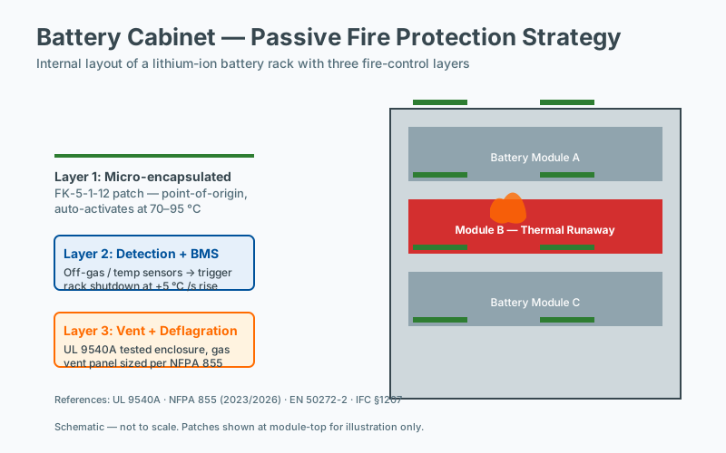 Battery cabinet fire protection layout
Thermal runaway is best understood as a positive feedback loop driven by exothermic chemistry inside a sealed cell. Once an initiating event raises a cell above a critical self-heating threshold, internal reactions begin releasing heat faster than the cell can dissipate it. The cell temperature rises, accelerating the reactions further, and the cycle continues until the cell vents, ignites, or explodes.
Common Initiating Events
- Internal short circuit caused by separator failure, dendrite growth, or manufacturing defects (e.g., metallic contamination during electrode coating)
- External short circuit from damaged busbars, flooded wiring conduits, or compromised battery management system (BMS) hardware
- Overcharging that drives lithium plating on the anode and accelerates SEI decomposition
- Mechanical abuse — impact, penetration, or vibration that deforms cell geometry and compromises the separator
- Thermal abuse from external heating, blocked cooling pathways, or adjacent cell failure
- Electrochemical abuse including excessive C-rates that generate internal heat faster than passive cooling can reject
The Thermal Runaway Temperature Curve
The transition from benign operation to catastrophic failure occurs across a relatively narrow temperature band, which varies modestly with cell chemistry:
| Temperature | Event |
|---|---|
| 60–80 °C | SEI (Solid Electrolyte Interphase) layer begins to decompose |
| 100–120 °C | Electrolyte breaks down; flammable vent gases begin to release |
| 130–150 °C | Separator (typically PE or PP) melts; internal short circuit develops |
| 150–200 °C | Cathode decomposition; transition metals catalyze further exotherms; oxygen release begins |
| 200 °C+ | Full thermal runaway; sustained combustion; potential cell rupture or explosion |
The critical engineering fact is this: once a cell crosses the thermal runaway threshold, the reaction is self-oxidizing. The cathode — particularly NMC (nickel manganese cobalt) and NCA (nickel cobalt aluminum) chemistries — releases lattice oxygen that supports combustion internally. No external suppression agent can meaningfully starve this internal reaction. Water, gas, powder, or aerosol simply cannot reach the chemistry that is sustaining the fire.
The objective of any fire protection strategy must therefore shift from extinguishment to containment, cooling, and propagation prevention.
Propagation: The Cabin-Level Threat
A single cell entering thermal runaway is a serious event. A propagating thermal runaway event — where one failing cell drives its neighbors into failure — is a facility-level emergency.
Cell-to-cell propagation depends on:
- Spacing: Tightly packed modules (typical 4–10 mm cell-to-cell gaps) propagate faster than widely spaced installations
- State of charge (SOC): Cells above 80% SOC store more energy and propagate more violently than cells at lower SOC
- Chemistry: LFP (lithium iron phosphate) chemistries generate lower propagation energies than NMC or NCA, but are not immune
- Module construction: Hard-shell prismatic cells and pouch cells behave differently under abuse; cylindrical cells (e.g., 18650, 21700, 4680) often vent through designated weak points
- Thermal management: Liquid-cooled modules reject heat more effectively than air-cooled designs
Industry testing standards such as UL 9540A (Test Method for Evaluating Thermal Runaway Fire Propagation) have been developed specifically to characterize this behavior at the cell, module, unit, and installation levels. Many AHJs now require UL 9540A test data before approving large BESS installations, particularly indoor or wall-mounted residential ESS.
Why Conventional Suppression Methods Fall Short
Most suppression technologies were developed for ordinary combustible fires — wood, paper, hydrocarbon liquids, electrical insulation. None of them were designed to address a self-oxidizing sealed chemical reactor.
Water and Sprinklers
Water-based suppression, including automatic sprinkler systems designed to NFPA 13, presents several specific problems in battery fires:
- Lithium-water reaction: Metallic lithium reacts with water to produce hydrogen gas and lithium hydroxide, both of which introduce additional ignition and corrosion hazards
- Electrical conductivity: Pooled water creates short-circuit risks across energized busbars, BMS boards, and inverter DC links — even after the source battery is disconnected
- Limited penetration: Water sprayed onto the exterior of a sealed battery module cannot reach the failing cells inside, particularly in IP-rated or liquid-cooled cabinets
- Re-ignition risk: Even after water application cools a surface, internal cell temperatures can remain high enough to reignite hours or days later
Dry Chemical Powder
ABC dry chemical (monoammonium phosphate) effectively knocks down flaming combustion, but in battery applications it:
- Coats exterior surfaces without penetrating cell interiors
- Leaves corrosive residue that may compromise BMS electronics, contactors, and current sensors
- Provides minimal sustained cooling once the powder settles
- Requires significant agent quantity to be effective at all
Clean Agent Gas Flooding
Gaseous agents such as Novec 1230 (FK-5-1-12), FM-200 (HFC-227ea), or inert gas systems (IG-541, IG-100) designed to NFPA 2001 are highly effective at total flood room protection for ordinary fires. In battery applications, however:
- Agent concentration is diluted long before reaching cells inside sealed modules
- Gas cannot remove heat from failing cells, only suppress external flame
- Once gas dissipates (typically within minutes), the battery continues off-gassing flammable vapor
- Enclosed cabinets may vent hot flammable gases into the protected room before the gas concentration has reached design levels
Aerosol Systems
Condensed aerosol systems (potassium nitrate-based, designed to NFPA 2010) deposit fine particulates that interrupt combustion chemistry. They offer longer residence time than gaseous agents but face similar limitations in reaching internal cell failures.
The Case for Passive, Localized Suppression
Because room-level suppression cannot reach the failing cell, the industry has increasingly turned to localized, automatically activated suppression — devices installed at the source of the anticipated fire, triggered by the heat of the cell itself rather than by room-level smoke detection.
Microencapsulated fire suppression patches represent one implementation of this approach. The active agent — typically FK-5-1-12 or a similar fluoroketone — is sealed inside a polymer or thermoplastic capsule engineered to rupture at a specific activation temperature (commonly 150–170 °C). When a cell reaches that threshold during thermal runaway, the capsule bursts and discharges the agent directly onto the failing module.
Why FK-5-1-12 for Battery Applications
FK-5-1-12 (chemical name: dodecafluoro-2-methylpentan-3-one) offers a specific set of properties that align well with battery fire protection:
- Zero ozone depletion potential and global warming potential of 1 (per IPCC AR6 assessment), making it compliant with environmental regulations including the EU F-Gas Regulation
- Electrically non-conductive — no risk to BMS boards, contactors, or energized DC busbars
- High heat of vaporization (≈ 88 kJ/kg) that absorbs substantial energy as it transitions from liquid to gas on contact with hot surfaces
- Low toxicity at design concentrations, with established safety margins per NFPA 2001
- No residue that requires cleanup or could damage sensitive electronics
- Long shelf life in sealed microencapsulation (typically 10+ years)
How the Cooling Mechanism Works
When the patch activates, the liquid agent contacts surfaces at or above its activation temperature. The agent vaporizes, and the phase change absorbs a large quantity of heat. This heat removal:
- Slows the rate of thermal propagation to adjacent cells
- Reduces peak cell and module temperatures
- Provides additional time for first responders, BMS shutdown, and gas evacuation systems
- Helps suppress external flaming by reducing vapor generation rates
The patch does not stop the runaway of the cell that has already failed — that chemistry is irreversible. Its value is in compartmentalization: containing the event to the smallest possible volume.
Deployment Considerations
Effective deployment of localized suppression requires engineering judgment based on cabinet volume, cell count, module configuration, and SOC management policy.
| Installation Type | Cabinet Size | Recommended Protection |
|---|---|---|
| 48 V telecom battery (LiFePO₄) | < 0.5 m³ | 1 patch, 170 °C activation |
| UPS battery cabinet | 0.5–1.5 m³ | 2 patches, 170 °C activation |
| Residential wall-mounted ESS | < 0.3 m³ | 1 patch, 170 °C activation |
| C&I ESS rack-mounted cabinet | 1.5–3 m³ | 3–4 patches per rack |
| Containerized BESS | Per-rack deployment | Patches on each rack, plus ventilation management |
Spacing of patches should account for module thermal geometry: a single patch installed above a vertically stacked module provides different coverage than a patch mounted adjacent to a horizontal cell array. Manufacturers’ engineering documentation should always be consulted for specific installation patterns, and AHJ approval may require third-party test data confirming coverage claims.
Integration With a Layered Battery Safety Strategy
No single technology can make a lithium-ion battery installation safe. Passive suppression is one layer in a defense-in-depth architecture that should also include:
Cell-level BMS monitoring. Modern BMS architectures monitor individual cell voltage, current, and temperature with millisecond resolution. Impedance trend tracking can identify cells drifting toward failure days or weeks before they enter self-heating. Reference standards: IEC 62619, UL 1973.
Adequate cell spacing and thermal barriers. Cell-to-cell spacing of 10 mm or more, combined with intumescent or aerogel-based thermal barriers between modules, can delay propagation long enough for suppression to activate. Reference: UL 9540A test data.
Active ventilation and gas detection. Failing cells vent flammable vapor (typically a mixture of CO, H₂, CH₄, C₂H₄, and electrolyte mists) well before sustained flaming. Hydrogen detectors calibrated to 25% LEL, combined with mechanical exhaust ventilation, can prevent gas accumulation to explosive concentrations. Reference: NFPA 855 for ESS installation ventilation requirements.
Deflagration venting. Cabinets and containers should incorporate pressure relief panels designed to NFPA 68 or EN 14491 to direct potential deflagration forces away from personnel and equipment.
Fire detection. Aspirating smoke detection (per NFPA 72) or early-warning gas detection can trigger facility-level alarms and BMS shutdown commands well before thermal runaway completes.
Site-level fire protection. Where required by NFPA 855, IFC Section 1207, or FM Global Property Loss Prevention Data Sheet 5-33, water-based or alternative suppression systems protect surrounding structures even when they cannot suppress the internal cell event.
Standards and Code Landscape
Several standards now govern how battery installations must be designed, tested, and protected:
- UL 9540 — Standard for Energy Storage Systems and Equipment
- UL 9540A — Test Method for Evaluating Thermal Runaway Fire Propagation
- NFPA 855 — Standard for the Installation of Stationary Energy Storage Systems
- NFPA 1 and IFC Section 1207 — Fire code requirements for ESS
- IEC 62619 — Secondary lithium cells for industrial applications
- EN 50549 and IEC 62933 — Grid connection and ESS system requirements
- FM Global DS 5-33 — Property Loss Prevention Data Sheet for lithium-ion BESS
AHJs increasingly require UL 9540A test reports as part of ESS permitting, particularly for indoor installations, wall-mounted residential ESS, and installations near occupied spaces.
Real-World Performance
Independent third-party testing conducted in 2024 at a certified fire laboratory evaluated a 48 V, 100 Ah LiFePO₄ battery module subjected to forced thermal runaway of three cells, protected by a single microencapsulated patch installed above the module:
- Activation: Patch ruptured at 168 °C (design activation temperature 170 °C)
- Propagation: Thermal runaway contained to the three triggered cells
- Adjacent cell temperatures: Remained below 100 °C with 4 cm cell spacing
- Flame propagation: No flame spread observed outside the module boundary
- Electronic integrity: BMS and wiring sustained only smoke exposure; no thermal damage
The result demonstrates that localized suppression can successfully compartmentalize a thermal runaway event in conditions where room-level suppression would have allowed full module involvement.
Frequently Asked Questions
What gas sensors detect early battery failure?
Early battery failure is typically detected through off-gas sensors that respond to the electrolyte vapor vented during the early stages of thermal runaway, well before cell temperature rises measurably. Commonly monitored species include hydrogen, carbon monoxide, and certain volatile organic compounds specific to the cell chemistry. Sensor placement inside the enclosure and a response threshold well below thermal-runaway temperature are required for the warning to be acted upon before propagation occurs.
What temperature triggers thermal runaway in Li-ion batteries?
There is no single thermal-runaway temperature for Li-ion cells; onset varies with chemistry, state of charge, age, and abuse condition. For most commercial cells, runaway onset typically occurs somewhere between 80 and 200 degrees Celsius, with self-sustaining exothermic reactions well above 150 degrees. Standards such as UL 9540A and IEC 62619 specify abuse tests rather than a single threshold, and suppression devices are designed to act before runaway onset is complete.
How does passive suppression differ from BMS-based protection?
A BMS detects electrical anomalies and disconnects at the cell or string level, but it relies on sensors, wiring, and control logic that can fail during the very event it is meant to manage. Passive suppression operates without external power or signal input: a thermally activated device releases its agent directly into the enclosure once a design threshold is reached. The two layers are complementary; the BMS limits fault propagation upstream, passive suppression contains the downstream thermal event.
Does passive suppression work for LFP as well as NMC batteries?
Both LFP (lithium iron phosphate) and NMC (nickel manganese cobalt) chemistries can undergo thermal runaway, though LFP typically releases less energy per cell and may not propagate as readily as NMC. Standards such as UL 1973 and IEC 62619 treat both chemistries as requiring propagation prevention, and UL 9540A is applied at the cabinet level regardless of chemistry. Suppression device selection should be based on the tested propagation behavior of the specific cabinet configuration rather than chemistry alone.