Overview
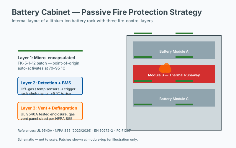 Cabinet layout — case study
Outdoor telecom sites in tropical and subtropical climates present a particular challenge for lithium-based energy storage. High ambient temperatures, limited ventilation, remote locations, and long emergency-response times combine to create conditions in which a single battery cell failure can cascade into a full cabinet loss. This case study documents one such event at a remote Southeast Asian tower site, in which a thermally activated suppression patch contained the event to three cells and prevented propagation to three additional battery strings and the adjacent radio-frequency (RF) equipment cabinet.
The case is broadly representative of incidents reported in NFPA and industry loss databases: lithium-ion and lithium iron phosphate (LiFePO₄) cabinet fires in telecom and edge-data-center applications are dominated by propagation scenarios, not by the initiating cell alone. The economics, downtime profile, and engineering lessons are therefore of immediate relevance to operators, integrators, and insurance risk engineers.
The Site
The site is a greenfield tower serving approximately 3,000 subscribers in a rural district of Southeast Asia. Climate data for the region places typical daily highs between 32 °C and 38 °C year-round, with relative humidity frequently above 80 %. The site is unstaffed and unmanned, with access requiring roughly two hours of driving on unpaved roads. Routine maintenance visits occur on a quarterly cadence, and there is no permanent fire-suppression water supply or automatic fire detection system beyond what is integrated into the cabinet itself.
The electrical architecture follows the standard operator template used across the network: a single outdoor cabinet houses a 48 V DC power system, with battery storage sized for an autonomy target of approximately 4 hours at the design load. Adjacent cabinets house RF transmission equipment, rectifiers, and microwave backhaul. The total site load is in the low single-digit kilowatts, which is typical of macro-cell sites in the region.
The Equipment
The battery cabinet under study has an internal volume of 1.2 m³ and houses four parallel battery strings, each rated at 100 Ah nominal capacity at 48 V. The cells are lithium iron phosphate (LiFePO₄), selected by the operator for its comparatively better thermal stability relative to nickel-manganese-cobalt (NMC) chemistries — a decision consistent with the guidance in UL 1973 and IEC 62619 for stationary energy storage applications. Each string is configured as a 16S assembly (16 cells in series), managed by a string-level battery management system (BMS).
Cabinet-level protection at the time of the incident consisted of:
- A string-level BMS with cell voltage, pack voltage, pack current, and cell temperature monitoring, with a stated response time to a hard cell-voltage fault of less than 200 ms.
- A thermo-mechanical venting path designed per UL 9540A test methodology to direct vented gas away from adjacent cells.
- One thermally activated fire suppression patch, rated to activate at 170 °C (±5 °C), secured to the interior ceiling of the cabinet above the battery compartment.
The patch is a self-contained, hermetically sealed device containing a clean-agent suppressant. Activation is purely thermal: at the design threshold, the device’s heat-sensitive element releases the agent directly into the enclosure, with no requirement for external power, signal wiring, or operator intervention. This design philosophy aligns with NFPA 10 § 1.2 and with the principles of NFPA 76 (now incorporated into NFPA 855 for energy storage systems) regarding the value of passive, non-electrical protection in unmanned or harsh-environment locations.
The Incident
At approximately 14:30 local time on a day with an ambient temperature of 38 °C, a single cell in Battery String 3 developed an internal short circuit. Internal short circuits in LiFePO₄ cells are typically the result of one or more of the following: separator failure due to lithium plating at charge, mechanical damage during handling or transport, dendrite growth across the separator over many cycles, or contamination introduced during cell manufacture. Regardless of root cause, the result is the same: a low-resistance current path forms inside the cell, Joule heating begins, and the cell enters self-sustaining exothermic reactions.
The BMS detected abnormal cell voltage — a divergence of more than 150 mV from the string average — and issued a fault flag. However, the fault was not isolated within the BMS reaction window: the contactor that would have disconnected String 3 from the DC bus did not open in time. By the time the BMS completed its diagnostic and protection cycle, the failing cell had already vented electrolyte gas and entered thermal runaway.
Thermal runaway in a single LiFePO₄ cell of this size releases an estimated 200–500 kJ of energy over 30–90 seconds, accompanied by vented gas containing hydrogen, methane, carbon monoxide, ethylene, and various fluorinated and phosphorus-bearing electrolyte decomposition products. The localized heat release raised the cabinet’s internal air temperature rapidly. At 168 °C, the thermally activated patch reached its activation threshold and released its suppressant charge into the cabinet interior.
Why Containment Worked
Containment in this incident is the result of three reinforcing engineering controls, not a single device:
Fast thermal detection without electrical dependency. The patch does not rely on sensors, wiring, or control logic. Its activation temperature is an intrinsic property of the device’s thermal element, so it cannot be defeated by a failed sensor, a BMS lockout, or a power outage at the cabinet. NFPA 72 and IEC 62619 both note that active detection-and-suppression systems for lithium battery enclosures require a level of integration that introduces additional failure modes; a properly specified passive device eliminates them.
Clean-agent chemistry compatible with live electronics. The suppressant released is electrically non-conductive, leaves no residue, and is characterized for use around energized equipment per NFPA 2001 and ISO 14520. This matters in a telecom cabinet because the adjacent RF equipment, rectifiers, and busbars remain energized throughout the event. A water-based or dry-chemical agent would have caused collateral damage to those systems even if it had successfully suppressed the battery fire.
Sizing and placement. A single patch was specified for the 1.2 m³ internal volume. The agent mass and discharge geometry are designed to achieve a design concentration sufficient to interrupt the radical-chain reactions of the vented electrolyte vapor within seconds of release. Placement on the interior ceiling — directly above the battery compartment — ensures that the discharged agent blankets the cell stack rather than being trapped in a corner.
Outcome
| Metric | Result |
|---|---|
| Cells affected | 3 cells in String 3 (entered thermal runaway) |
| Cells saved | 13 remaining cells in String 3 + all cells in Strings 1, 2, 4 |
| Adjacent cabinet damage | None |
| Site downtime | 6 hours (replace String 3 + BMS module) |
| Patch activation temperature | 168 °C (design: 170 °C ± 5 °C) |
| Suppression time | < 2 seconds from activation |
The three affected cells were destroyed. The remaining thirteen cells in String 3, and all cells in Strings 1, 2, and 4, were recovered without measurable capacity loss on subsequent acceptance testing. The cabinet enclosure showed localized soot and heat marking on the interior ceiling and on the immediate area around String 3, but no breach of the cabinet wall, no burn-through of the cabling, and no propagation of flame or heat to the adjacent RF cabinet separated by approximately 300 mm of free air.
Total downtime was six hours. Recovery consisted of replacing String 3 as a pre-charged assembly, swapping the BMS module for a recalibrated unit, and performing a standard commissioning sequence. Subscribers experienced no loss of service because the remaining three strings carried the site through the recovery window.
What Would Have Happened Without Suppression
Comparison with documented loss events at unprotected sites in similar climates suggests the likely counterfactual. Thermal runaway in a LiFePO₄ cell typically propagates to neighboring cells within 30–180 seconds in the absence of an active barrier, through a combination of radiant heat, convective heating of vented gas, and direct cell-to-cell thermal conduction across busbars and module housings. Once a second cell in the same string vents, the probability of full-string involvement within five minutes is high, and once the string is fully involved, propagation to adjacent strings is probable within ten to fifteen minutes.
The likely outcome at this site, had no suppression device been present, is:
- Complete loss of all four battery strings (estimated 80–95 % probability).
- Breach of the cabinet wall or door by the overpressure event typical of multi-cell propagation (per UL 9540A data, a 16S string in full runaway can produce 50–100 kPa peak overpressure inside an unvented enclosure).
- Flame impingement on the adjacent RF cabinet through the 300 mm air gap.
- Total site loss requiring cabinet replacement, RF equipment replacement, and full re-commissioning.
- Downtime of 7 to 14 days, limited by road access during the response window and parts availability.
- Direct equipment replacement cost in the range of $35,000, exclusive of lost revenue, customer credits, and possible regulatory reporting obligations under local fire codes.
The economic comparison between a passive device in the low-hundreds of dollars and a $35,000+ loss event is the central argument for this class of protection. It is also consistent with the loss-prevention guidance in NFPA 855 § 4.6 for ESS installations in remote or unattended locations.
Engineering and Standards Context
This incident illustrates several principles that are codified across the relevant standards landscape:
- NFPA 855 (Standard for the Installation of Stationary Energy Storage Systems) treats propagation prevention as the primary objective for lithium-based ESS. The hierarchy is: chemistry selection, physical separation, thermal barriers, then active suppression. A thermally activated patch acts primarily at the barrier level and secondarily as a suppression layer.
- UL 9540A is the test method that determines whether a given ESS can be considered to have passed the cell-to-cell propagation criterion at the cabinet level. Test data from this method is increasingly required by Authorities Having Jurisdiction (AHJs) before commissioning.
- IEC 62619 specifies requirements for secondary lithium cells used in industrial applications, including the thermal abuse tests (external heating, internal short) that characterize runaway propagation.
- NFPA 2001 / ISO 14520 govern clean-agent fire extinguishing systems, including the design concentrations, hold times, and compatibility requirements relevant to the suppressant in this case.
- UL 1973 covers batteries for use in stationary and motive auxiliary power applications, including the cell-level abuse testing baseline.
Operators specifying protection for similar sites should ensure that any candidate device is independently tested and listed, that activation temperature is documented with tolerance, and that the agent is appropriate for the cabinet volume and for the presence of energized electronics.
Key Takeaway
A single passive suppression patch costing in the low hundreds of dollars prevented an event that, on the available evidence from comparable unprotected sites, would have caused tens of thousands of dollars in equipment loss and one to two weeks of downtime. The activation temperature recorded during the incident (168 °C) was slightly conservative against the 170 °C design point — well inside the ±5 °C tolerance band — confirming that the device performed as specified and validating the engineering conservatism built into its design.
For operators of remote or unmanned telecom, edge data, and distributed energy sites in hot climates, the lessons are clear: design protection around the propagation event, not the initiating cell; prefer devices that function independently of site power and BMS health; and verify that any suppression measure is compatible with the chemistry present and the electronics exposed.
Frequently Asked Questions
What temperature triggers thermal runaway in Li-ion batteries?
There is no single thermal-runaway temperature for Li-ion cells; onset varies with chemistry, state of charge, age, and abuse condition. For most commercial cells, runaway onset typically occurs somewhere between 80 and 200 degrees Celsius, with self-sustaining exothermic reactions well above 150 degrees. Standards such as UL 9540A and IEC 62619 specify abuse tests rather than a single threshold, and suppression devices are designed to act before runaway onset is complete.
How does passive suppression differ from BMS-based protection?
A BMS detects electrical anomalies and disconnects at the cell or string level, but it relies on sensors, wiring, and control logic that can fail during the very event it is meant to manage. Passive suppression operates without external power or signal input: a thermally activated device releases its agent directly into the enclosure once a design threshold is reached. The two layers are complementary; the BMS limits fault propagation upstream, passive suppression contains the downstream thermal event.
Does passive suppression work for LFP as well as NMC batteries?
Both LFP (lithium iron phosphate) and NMC (nickel manganese cobalt) chemistries can undergo thermal runaway, though LFP typically releases less energy per cell and may not propagate as readily as NMC. Standards such as UL 1973 and IEC 62619 treat both chemistries as requiring propagation prevention, and UL 9540A is applied at the cabinet level regardless of chemistry. Suppression device selection should be based on the tested propagation behavior of the specific cabinet configuration rather than chemistry alone.
Can a fire in one battery cell spread to adjacent cells?
Yes. Once a cell enters thermal runaway, vented gas and radiant heat can propagate failure to neighboring cells within seconds to minutes, depending on cell spacing, state of charge, and module geometry. UL 9540A testing characterizes this propagation behavior at the cabinet level, and NFPA 855 treats propagation prevention as a primary design objective for stationary energy storage. Physical separation, thermal barriers, and suppression devices are commonly combined to interrupt the propagation chain.