The market for point-of-origin fire suppression has expanded significantly over the past decade, driven by the proliferation of sensitive electronics in compact enclosures — from server racks and telecommunications cabinets to EV charging stations, battery storage systems, and industrial control panels. Three distinct technologies now compete for this same niche: microencapsulated suppression patches, condensed aerosol generators, and fire detection tube systems. All three share the same fundamental objective — automatic, localized fire suppression without reliance on building-level sprinkler infrastructure — but they achieve it through fundamentally different physical and chemical mechanisms.
Understanding these differences is not academic. The choice of technology determines whether the fire is suppressed and the equipment survives, or whether the fire is suppressed but the protected asset is damaged by the very system that saved it. This article provides an engineering-level comparison of all three approaches, with reference to applicable standards, real-world performance data, and selection guidance for facility managers, electrical engineers, and fire protection designers.
Technology Overview
 Patch vs aerosol vs fire tube
Microencapsulated Suppression Patches
A microencapsulated suppression patch is a solid polymer matrix in which droplets of a clean extinguishing agent — most commonly FK-5-1-12 (C₆F₁₂O, also designated Novec 1230 by 3M, although equivalent grades are available from multiple manufacturers) — are sealed within thermally rupturable microcapsules. The patch is adhered directly to the interior of the enclosure or to a component surface using a pressure-sensitive adhesive backing.
When ambient temperature at the patch surface reaches the activation threshold — typically 170 °C, though other set points between 100 °C and 250 °C are available — the microcapsule walls soften and rupture, releasing the agent as a vapor. The agent floods the local volume and interrupts combustion through the same heat-absorption (physical) mechanism used by any clean agent: vaporization extracts energy from the flame zone while the vapor itself displaces oxygen below the stoichiometric threshold required for sustained combustion.
Key characteristics:
- Zero electrical power required for activation or monitoring
- Zero scheduled maintenance during service life
- 10-year typical service life (some manufacturers rate products for 15 years)
- No residue — the agent vaporizes completely and dissipates with ventilation
- Activation at 170 °C standard (customizable in 10 °C increments)
- Peel-and-stick installation — typically under five minutes per unit
- No pressure vessel, no moving parts, no pyrotechnic charge
The technology aligns conceptually with the performance expectations of NFPA 2001 (Clean Agent Fire Extinguishing Systems) and ISO 14520 for FK-5-1-12, although the patch form factor falls outside the scope of total-flooding system design standards. Manufacturers typically submit products to UL 2775 or similar third-party test programs to verify discharge performance, concentration, and electrical non-conductivity.
Condensed Aerosol Generators
A condensed aerosol generator is a sealed metal canister containing a solid pyrotechnic compound — most commonly a mixture of potassium nitrate, an organic binder, and a reducing agent. When initiated by an electrical signal from a separate detection circuit, or in some designs by a thermal element, the compound ignites and combusts rapidly to produce a dense cloud of fine particulate aerosol, predominantly potassium carbonate (K₂CO₃), potassium hydroxide (KOH), and various intermediate species.
The aerosol interrupts combustion through chemical (flame inhibition) action: potassium radicals react with the free radicals (H•, OH•, O•) that propagate the flame chain reaction. This is a fundamentally different mechanism from clean agents, which act primarily by heat absorption and oxygen displacement. Because the chemical action is highly efficient at low concentrations, aerosol generators can protect relatively large volumes from compact hardware.
Key characteristics:
- Electrically or thermally activated — most installations use a linear heat detector or spot detector wired to the unit
- Produces a dense aerosol cloud that fills the enclosure volume
- Leaves potassium-based residue on all surfaces within the protected volume
- Service life 10–15 years — the solid compound does not degrade in storage
- Hot discharge — the aerosol exits the generator at 200–400 °C, requiring standoff distances from components
- Pyrotechnic content — shipping, storage, and disposal may be regulated under UN classification 1.4S or similar
Applicable standards include UL 2775, NFPA 2010 (Standard for Fixed Aerosol Fire-Extinguishing Systems), and ISO 15779. Aerosol technology is widely deployed in engine compartments, electrical cabinets, and marine machinery spaces, particularly where weight and volume efficiency matter more than post-event cleanliness.
Fire Detection Tubes (Linear Pneumatic Detection Systems)
A fire detection tube system — sometimes called a “Firetrace” system after a major brand, though multiple manufacturers offer equivalent designs — combines linear detection and agent delivery in a single component. The system consists of a small-diameter polymer tube (typically 6–10 mm) routed throughout the enclosure, pressurized with nitrogen to approximately 15–20 bar, and connected to a storage cylinder containing the suppression agent.
The tube is the detector. When a fire heats any point along its length to approximately 100–180 °C (depending on tube rating), the polymer softens and bursts at the hottest spot. The sudden pressure drop triggers a valve on the storage cylinder via a pneumatic or mechanical linkage, releasing the agent through the rupture and throughout the enclosure.
Key characteristics:
- Heat-activated linear detection — the tube follows the contours of the protected volume
- Tube burst at 100–180 °C — different tube grades suit different thermal environments
- Agent stored in pressurized cylinder — typically dry powder or a clean agent
- Requires periodic pressure checks and, in many jurisdictions, formal 5- or 10-year hydrostatic requalification of the cylinder
- Installation complexity — tube must be routed without kinks, secured at intervals, and connected to the cylinder with appropriate fittings
Reference standards include NFPA 17A (Wet Chemical Extinguishing Systems), NFPA 2001 for clean agent variants, and various regional codes for pressure vessel inspection. In some jurisdictions, the cylinder falls under the Pressure Equipment Directive (PED 2014/68/EU) or ASME Boiler and Pressure Vessel Code requirements.
Comparison Matrix
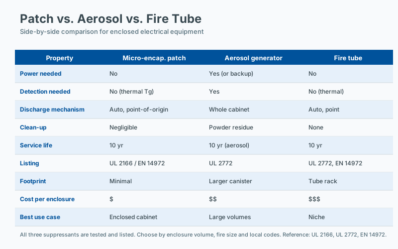
The table below summarizes the principal technical and operational parameters across the three technologies.
| Factor | Patch | Aerosol | Fire Tube |
|---|---|---|---|
| Agent type | FK-5-1-12 (clean) | Potassium-based aerosol | Dry powder or clean agent |
| Residue | None | Heavy white/yellow powder | Varies by agent |
| Activation threshold | 170 °C (customizable) | Electrical or heat signal | Tube burst at 100–180 °C |
| Power required | No | Usually yes (detection circuit) | No (for detection; agent release mechanical) |
| Installation time | 5 minutes | 30+ minutes (mount + wire) | 1–2 hours (route tube + mount cylinder) |
| Service life | 10 years (typical) | 10–15 years | 5–10 years (depends on cylinder requalification) |
| Scheduled maintenance | None | Minimal; check initiator circuit | Annual pressure check; 5–10 yr cylinder test |
| Coverage pattern | Point source | Enclosure-wide cloud | Linear along tube path |
| Approximate unit cost (USD) | $30–$200 | $100–$500 | $200–$800 |
| Electronics-safe post-event | Yes | No (corrosive residue) | Depends on agent |
| False activation risk | Very low (heat-only) | Low | Low–medium (tube leak, mechanical damage) |
Electronics Compatibility: The Deciding Factor
For the dominant use case — point-of-origin protection of enclosed electrical and electronic equipment — the single most important differentiator between the three technologies is the post-event state of the protected equipment. Suppression is only half the job; preservation of the asset is the other half, and the two are not the same thing.
Patches: Zero Impact
FK-5-1-12 has an atmospheric lifetime of approximately 16 days, a global warming potential of less than 1, and zero ozone depletion potential. It is electrically non-conductive in its vapor phase and leaves no residue whatsoever. Following discharge and brief ventilation — typically 5 to 15 minutes depending on enclosure volume — servers, switches, printed circuit boards, and other electronic assemblies can be inspected and returned to service. No cleaning is required, no components need replacement, and no corrosion mechanism is initiated. For mission-critical facilities such as data centers, telecommunications central offices, and financial trading floors, this property is not merely desirable; it is operationally essential.
Aerosols: High Impact
The chemical efficacy of potassium-based aerosols comes with a significant cost: the residue. The discharge products are predominantly potassium carbonate (K₂CO₃) and potassium hydroxide (KOH), both of which are strongly alkaline and hygroscopic. When these compounds deposit on a printed circuit board, they form a thin conductive film that absorbs moisture from the air. The consequences include:
- Short circuits between closely spaced traces (typical PCB line spacing of 0.2 mm or less is highly vulnerable)
- Galvanic corrosion of copper pads, plated through-holes, and solder joints
- Dendritic growth between conductors under bias
- Progressive failure of components over hours to days after the event
A documented European telecommunications operator evaluated an aerosol system in a decommissioned switch cabinet. The fire was suppressed within seconds; however, post-event testing showed that all twelve line cards failed within 72 hours despite professional cleaning with isopropyl alcohol and deionized water. The conductive film had penetrated under BGA packages and into connector housings, where it could not be reliably removed.
This does not mean aerosol systems are unsuitable for all applications. They remain an excellent choice for engine compartments, generator sets, marine machinery spaces, and other enclosures where the protected contents are mechanical rather than electronic, and where the residue can be tolerated or easily cleaned.
Fire Tubes: Variable Impact
The residue profile of a fire tube system depends entirely on the agent stored in the cylinder. Dry chemical powders — typically monoammonium phosphate or ABC powder — produce heavy residue similar to handheld extinguishers, with the same corrosive and insulative effects on electronics. Clean agent variants using FK-5-1-12 or HFC-227ea (FM-200) avoid this issue entirely but are less common, more expensive, and subject to the same HFC phase-down pressures that are reshaping the clean agent market under the EU F-Gas Regulation.
When Each Technology Excels
No single technology is optimal for every application. The following guidance reflects typical selection criteria.
| Scenario | Best Choice | Reasoning |
|---|---|---|
| Server racks, IT equipment, network switches | Patch | Zero residue; immediate recovery possible |
| Electrical panels (non-IT, e.g., motor starters) | Patch or Aerosol | If residue tolerable, aerosol works; otherwise patch |
| Large enclosures (>3 m³) | Fire Tube or multiple patches | Tube covers larger volume linearly |
| Outdoor cabinets (dusty/humid) | Aerosol or Patch | Tube may be affected by UV, condensation, mechanical damage |
| Battery cabinets (Li-ion) | Patch | Clean agent does not react with lithium; important for thermal runaway scenarios |
| Budget-constrained, non-critical | Aerosol | Lowest acquisition cost for non-sensitive equipment |
| Custom-shaped enclosures | Fire Tube | Linear routing adapts to any geometry |
| Engine compartments, gensets | Aerosol | High-temperature tolerance, effective on flammable liquid fires |
Standards and Regulatory Context
Specifying any of these technologies requires awareness of the applicable code framework. NFPA 2001 and ISO 14520 cover clean agent total-flooding systems but were written primarily for room-scale protection, not point-of-origin patch applications. NFPA 2010 specifically addresses condensed aerosol systems. UL 2775 is the principal U.S. third-party listing standard for both clean agent and aerosol point-of-origin units.
In the European Union, the Construction Products Regulation (CPR, EU 305/2011) governs products with a fire protection function, and CE marking under EN 15276-2 applies to aerosol units. Pressure vessels associated with fire tube systems fall under the Pressure Equipment Directive (PED, 2014/68/EU). FM Global Approval is often required by insurers for larger installations. Designers should also consider jurisdictional requirements for the storage, transport, and end-of-life disposal of pyrotechnic aerosol compounds, which may be classified as explosives precursors under some national regulations.
The Verdict
For the dominant use case of point-of-origin suppression of enclosed electronics — server rooms, telecommunications cabinets, control panels, battery enclosures — microencapsulated suppression patches represent the most operationally robust solution. The combination of zero residue, zero scheduled maintenance, zero electrical power, and installation simplicity is unmatched by either of the competing technologies.
Condensed aerosol systems are highly capable of extinguishing fires but consistently fail the “protect the equipment, not just the fire” test for sensitive electronics. Fire detection tubes offer excellent spatial coverage flexibility and remain valuable for irregular geometries and large volumes, but introduce installation complexity, maintenance obligations, and — depending on agent — residue concerns.
The technology choice should follow from a clear-eyed assessment of what must be protected, what residue the protected contents can tolerate, and what lifecycle costs the facility can sustain.
Frequently Asked Questions
Can two different suppression technologies be used in the same enclosure?
In principle, yes, if both are designed for the same protected volume and the combined agent concentrations remain within the safety limits for the enclosure. In practice, interaction effects between agents are not always well characterized, and most manufacturers recommend a single primary technology per enclosure. Engineering analysis and AHJ acceptance are required for hybrid designs.
What is the most overlooked factor in suppression technology selection?
Compatibility of the suppression agent with the equipment being protected: electrical compatibility for energized systems, residue tolerance for clean-electronics environments, and pressure-rise tolerance for sealed enclosures. Many selection decisions focus on agent volume and ignore these compatibility questions until after an incident.
How do ambient conditions affect suppression technology choice?
Ambient temperature, humidity, and ventilation all affect the performance of both the fire (ignition likelihood, growth rate) and the suppression system (agent concentration retention, device activation timing). Enclosures in high-temperature or high-humidity environments may need devices with higher activation temperatures and corrosion-resistant construction. Manufacturer data should be reviewed against the actual installation environment.
How do I evaluate which technology fits my specific hazard?
Start with a structured risk assessment: identify the fire load, credible ignition sources, and propagation pathways. Then match the suppression technology's tested performance to that hazard profile (enclosure volume, fire growth class, agent compatibility, and installation environment). Standards-based engineering judgment, supported by manufacturer data and third-party listings, is more reliable than generic comparison tables.