Understanding UL 9540A: Thermal Runaway Testing for Battery Systems
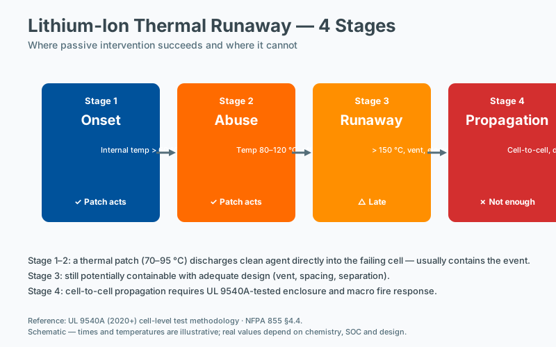 Thermal runaway test stages
Introduction
Lithium-ion battery energy storage systems (BESS) have become foundational to modern electrical infrastructure, supporting residential solar integration, commercial peak shaving, utility-scale renewables, and mission-critical backup power. Their proliferation has, however, introduced a critical safety question: what happens when a single cell goes into thermal runaway, and can that failure propagate to neighboring cells, modules, and units with catastrophic consequences?
The answer to that question is the purpose of UL 9540A, Standard for Test Method for Evaluating Thermal Runaway Fire Propagation in Battery Energy Storage Systems. Published by Underwriters Laboratories, UL 9540A is not a listing or certification standard like UL 9540 or UL 1973. It is a test method—a detailed, multi-level procedure designed to characterize how a specific battery product behaves when subjected to thermal runaway. Its outputs inform installers, code officials, and authorities having jurisdiction (AHJs) about whether a given BESS can be safely deployed in a given location.
This article provides an in-depth technical examination of UL 9540A. It explains the standard’s purpose, walks through each of its four progressive test levels, examines the gas composition and deflagration analyses, clarifies how UL 9540A outputs connect to NFPA 855 and the International Fire Code (IFC), and distinguishes UL 9540A from its companion standards UL 9540 and UL 1973.
1. What UL 9540A Is—and What It Is Not
UL 9540A was first introduced in 2017 and has undergone multiple revisions, with the 5th edition (released in 2024) being the current version at the time of writing. The standard establishes a methodology to evaluate whether—and under what conditions—thermal runaway initiated in a single cell can propagate to adjacent cells, modules, or units.
UL 9540A is:
- A performance test method, not a product standard or listing standard.
- A means of generating empirical data on fire behavior, gas generation, and explosion hazard.
- A reference used by installation codes (NFPA 855, IFC Section 1207) to determine spacing, enclosure, and protection requirements.
UL 9540A is not:
- A pass/fail certification. The standard does not declare a product “approved” or “failed”; rather, it documents observed behavior. The interpretation of results is the responsibility of code officials and listing engineers.
- A replacement for UL 9540 system-level safety certification.
- A universal yardstick: results apply to the specific product configuration tested, including cell chemistry, module design, BMS firmware version, and packaging.
2. The Origin of the Standard
Lithium-ion cell thermal runaway was rarely a regulatory consideration before 2012, when a series of high-profile incidents—including Boeing 787 Dreamliner groundings and several BESS fires in the United States and Asia—drew attention to the unique hazards of large-format lithium-ion installations. The 2019 McMicken BESS fire in Arizona, which caused injuries to four firefighters, accelerated code adoption.
UL 9540A was developed in parallel with NFPA 855, Standard for the Installation of Stationary Energy Storage Systems. NFPA 855 references UL 9540A test data explicitly to determine when large fire protection setbacks can be reduced or eliminated, particularly for indoor and rooftop installations.
3. The Four Test Levels
UL 9540A employs a hierarchical, bottom-up methodology. Testing begins at the smallest scale (cell) and only progresses upward if the previous level’s results warrant it. This tiered approach conserves cost and time: if thermal runaway does not propagate at the cell level, subsequent propagation testing may not be required.
3.1 Cell Level
Objective: Determine whether a single cell can be driven into thermal runaway, characterize the resulting gas composition, and measure the cell’s heat release and mass loss.
Procedure:
- A representative cell (the same chemistry, capacity, and form factor used in the final product) is instrumented with thermocouples and voltage sensors.
- The cell is brought to 100% state of charge (SOC), typically at the manufacturer’s maximum specified SOC.
- Thermal runaway is initiated using one of several methods:
- Nail penetration (mechanical abuse)
- Heater cartridge (thermal abuse)
- Overcharge (electrical abuse)
- Initiation is confirmed when the cell exhibits a sustained exothermic reaction—typically defined by a rapid temperature rise exceeding 10°C per second, vent gas release, and/or a sharp drop in terminal voltage.
- Cell surface temperature, vent gas volume, and gas composition are recorded throughout the test.
Key outputs:
- Whether thermal runaway can be reliably initiated.
- The cell’s peak temperature during runaway.
- Total heat release and heat release rate.
- Total gas volume generated.
- Gas composition (see Section 5).
3.2 Module Level
Objective: Determine whether thermal runaway propagates from the initiating cell to adjacent cells within the same module.
Procedure:
- A representative module is fully populated with cells at 100% SOC.
- A single cell—typically located in the geometric center or worst-case location—is forced into thermal runaway using the same method that succeeded at the cell level.
- Thermal runaway is confirmed via instrumentation.
- Temperatures of all adjacent cells are monitored to detect propagation.
Key outcomes:
- Propagation — If runaway spreads to one or more adjacent cells, the result is a propagating module failure.
- Non-propagation — If runaway is confined to the initiating cell with no propagation to neighbors, the module passes the propagation criterion.
Additional measurements:
- Surface temperature of the module enclosure.
- Heat release rate at the module level using oxygen consumption calorimetry.
- Total smoke and gas release.
- Photographs and video of vent behavior, smoke production, and any flaming or ejection of cell materials.
If propagation does not occur at the module level, the test report can document the lack of propagation, and unit-level and installation-level testing may not be required. If propagation does occur, the standard prescribes a protocol for retesting with proposed mitigation features (e.g., thermal barriers, intumescent materials, cell-level fuses, BMS interventions).
3.3 Unit Level
Objective: Evaluate the behavior of a complete BESS unit (the smallest shippable assembly containing modules, BMS, thermal management, and enclosure) when subjected to module-level thermal runaway.
Procedure:
- A full BESS unit is installed in a fire test facility, often beneath a large hood with exhaust calorimetry.
- Depending on module-level results, one or more modules within the unit are forced into thermal runaway.
- The unit-level test assesses:
- Whether runaway propagates between modules within the unit.
- Heat release rate at the unit scale.
- Gas generation and composition within the unit enclosure.
- Whether the unit enclosure vents hot gases, smoke, or flames in a manner that creates hazards beyond the unit footprint.
Key outputs:
- Total unit-level heat release rate, used to size fire suppression and ventilation.
- Whether hot gas ejection from the unit occurs and its temperature/flammability.
- Evidence of flaming outside the enclosure.
3.4 Installation Level
Objective: Characterize the behavior of a complete installation—either an array of BESS units or a unit within a representative room, enclosure, or container—when subjected to a unit-level thermal runaway event.
Procedure:
- The installation is built to mimic the field deployment as closely as practical: actual spacing, wall construction, ceiling height, ventilation, suppression systems, and gas detection.
- A unit within the installation is forced into thermal runaway.
- Sensors throughout the installation record temperatures, gas concentrations, and radiation levels.
- The test verifies whether the runaway event remains contained to the initiating unit or whether fire or explosion propagates to adjacent units or the surrounding space.
Key outputs:
- Heat release rate at the installation scale.
- Gas accumulation in the room or enclosure, particularly hydrogen and methane concentrations relative to the lower flammability limit (LFL).
- Wall and ceiling surface temperatures, used to assess fire spread to building structure.
- Pressure rise and potential for deflagration (see Section 6).
Installation-level testing is most often used to justify reduced spacing, alternative compliance pathways, or for large-scale systems where simple setback compliance would be impractical.
4. Thermal Runaway Propagation: Mechanisms and Metrics
Thermal runaway in a lithium-ion cell occurs when internal heat generation exceeds the cell’s ability to dissipate it, leading to a self-accelerating exothermic decomposition of the cell’s anode, cathode, electrolyte, and separator. Typical triggers include internal short circuits, mechanical damage, external heating, overcharge, and manufacturing defects.
Propagation between cells depends on multiple factors:
- Heat transfer mode — conduction through cell casings, radiation from hot surfaces, convection from vent gases.
- Cell spacing and packaging — closer spacing or shared thermal mass favors propagation.
- State of charge — higher SOC means more stored energy and more vigorous runaway.
- Cell chemistry — NMC cathodes generally release more energy than LFP; LFP is less energetic but can still propagate.
- Mitigation features — thermal barriers, intumescent coatings, active cooling, and BMS shutdown can interrupt propagation.
UL 9540A quantifies propagation risk through direct observation: did neighboring cells also runaway, or did their temperatures plateau below the runaway threshold?
5. Gas Composition Analysis
One of UL 9540A’s most important outputs is the characterization of vent and combustion gases. Lithium-ion cell thermal runaway generates a complex mixture including:
- Hydrogen (H₂) — typically the most concerning species; LFL of 4% by volume in air.
- Methane (CH₄) — LFL of 5%.
- Carbon monoxide (CO) — toxic and combustible; LFL of 12.5%.
- Ethylene (C₂H₄) — LFL of 2.7%.
- Propane (C₃H₈) — LFL of 2.1%.
- Hydrogen fluoride (HF) — produced from fluorinated electrolytes; highly toxic at low concentrations (e.g., 30 ppm is immediately dangerous to life).
- Carbonyl fluoride, phosphoryl fluoride, and additional electrolyte decomposition products.
- CO₂ — from combustion of organic vapors.
UL 9540A requires gas sampling using Fourier-transform infrared (FTIR) spectroscopy, gas chromatography, electrochemical sensors, or bag sampling with laboratory analysis. The standard specifies the timing, location, and methodology for sampling, and requires reporting of species concentrations as both peak and time-integrated values.
Why this matters for design: If the test shows significant hydrogen generation, the BESS enclosure must incorporate active or passive ventilation capable of diluting the gas below 25% of LFL (a typical safety margin). If HF is detected, the installation may require toxic gas detection, specialized suppression agents, and enhanced fire department notification.
6. Deflagration Hazard Assessment
Beyond fire propagation, UL 9540A addresses the deflagration (explosion) hazard. When vent gases accumulate in an enclosure or room faster than they can be diluted or exhausted, the mixture can enter the flammable range. A subsequent ignition source—whether a spark from a relay, a hot surface, or the runaway event itself—can cause a deflagration with potentially devastating overpressure effects.
UL 9540A’s installation-level test measures:
- Peak gas concentrations of each combustible species relative to its LFL.
- Time to reach 25% LFL in the test volume (used to size gas detection response times).
- Overpressure if ignition occurs.
- Vent area effectiveness in relieving deflagration pressure.
If the installation test demonstrates that gas concentrations remain well below LFL due to adequate ventilation or enclosure design, the deflagration hazard may be considered adequately mitigated. If concentrations approach or exceed LFL, additional measures—such as deflagration venting panels, increased mechanical ventilation, or gas detection with automatic shutdown—may be required by the AHJ.
7. How UL 9540A Connects to NFPA 855 and the IFC
NFPA 855 (2023 and 2026 editions) and IFC Section 1207 establish prescriptive requirements for the installation of stationary energy storage systems. Key provisions include:
- Maximum stored energy limits based on location and technology.
- Spacing (setback) requirements between BESS units, walls, and property lines.
- Fire suppression requirements.
- Ventilation and gas detection requirements.
- Special requirements for indoor, rooftop, and below-grade installations.
NFPA 855 allows certain prescriptive provisions to be modified when UL 9540A test data demonstrates that equivalent or superior safety is achieved. For example:
- If a BESS demonstrates non-propagating module-level behavior and unit-level heat release below defined thresholds, NFPA 855 may permit reduced unit-to-unit spacing (or no spacing at all).
- If gas analysis confirms that no combustible gases reach 25% LFL during the unit-level test, NFPA 855 may allow reduced or no mechanical ventilation.
- If installation-level testing demonstrates that fire does not propagate to adjacent units, larger aggregate energy capacities may be permitted in a single fire area.
In practice, an AHJ reviewing a BESS permit application will typically require:
- A UL 9540 system listing demonstrating compliance with the full system standard.
- A UL 9540A test report from a Nationally Recognized Testing Laboratory (NRTL).
- The manufacturer’s installation manual specifying the conditions under which the test data is valid (cell model, BMS firmware, configuration, SOC limits).
- A site plan demonstrating compliance with the conditions of the UL 9540A report and any NFPA 855 modifications.
Without UL 9540A data, the BESS must comply with the strictest prescriptive NFPA 855 provisions, which can be impractical for large installations.
8. AHJ Approval: Reading a UL 9540A Report
A UL 9540A report is a dense technical document. An experienced reviewer (often a fire protection engineer or plans examiner) will examine it for several critical items:
- Tested cell chemistry, capacity, and form factor — must match the deployed product exactly.
- Tested module configuration — including cell count, arrangement, BMS firmware version, and any thermal management features.
- Initiation method — nail, heater, or overcharge—and the rationale for selecting that method.
- Propagation status — clearly stated as propagating or non-propagating at each level.
- Peak heat release rate — at module and unit levels, used to verify NFPA 855 compliance.
- Gas generation data — including species concentrations and time to reach 25% LFL.
- Tested installation geometry — if installation-level testing was performed.
- Limitations and conditions — the manufacturer must specify any configuration changes that invalidate the report.
- Date of test — many AHJs require testing within the past 3–5 years, given the pace of product evolution.
The AHJ retains the right to require additional testing, impose more conservative interpretations, or reject the report if any condition is not satisfied.
9. UL 9540 vs. UL 9540A vs. UL 1973
These three standards are frequently confused but serve distinct purposes.
| Standard | Scope | Type | Purpose |
|---|---|---|---|
| UL 1973 | Battery cells, modules, and packs used in stationary and motive applications | Product safety standard | Evaluates electrical, mechanical, and environmental safety at the component level. |
| UL 9540 | Complete BESS, including power conversion, controls, and ancillary equipment | System safety standard | Evaluates safety of the integrated system, including electrical safety, functionality, and system-level hazards. |
| UL 9540A | Cell, module, unit, and installation-level behavior under thermal runaway | Test method | Generates data on fire propagation, gas generation, and explosion hazards. |
In short:
- UL 1973 addresses the battery component itself.
- UL 9540 addresses the BESS as a system.
- UL 9540A addresses the BESS’s behavior under worst-case abuse conditions.
A complete compliance package for a US installation typically includes UL 1973 (cell/module), UL 9540 (system), and UL 9540A (fire behavior), along with compliance with NFPA 855 (or IFC Section 1207) for the installation itself.
10. Limitations and Common Misunderstandings
Several recurring misunderstandings are worth addressing:
- “UL 9540A approval” is a misnomer. No entity “approves” a product under UL 9540A; the standard produces test data. The AHJ evaluates whether that data demonstrates compliance with the installation code.
- A passing UL 9540A report does not guarantee zero risk. The test is designed to characterize behavior under specific abuse conditions; it cannot anticipate every possible failure mode in the field.
- Test data is product-specific. A change in cell supplier, BMS firmware, or even a minor housing modification may invalidate prior test results.
- UL 9540A is not a substitute for UL 9540 system certification. Many jurisdictions require both.
- Internationally, UL 9540A is one of several recognized test methods. IEC 62619, IEC 62933-5-2, and other standards address similar concerns but use different methodologies. Some jurisdictions outside the US accept UL 9540A data; others do not.
11. Practical Guidance for Manufacturers, Integrators, and AHJs
For manufacturers:
- Design thermal runaway mitigation into the product from the earliest stages—cell-to-cell spacing, thermal barriers, vent paths, and BMS-controlled isolation all matter.
- Test conservatively: use the highest SOC, the worst-case cell location, and the most adverse installation geometry supported by the product.
- Document configuration control carefully; any change requires evaluation for impact on prior test data.
For integrators and design professionals:
- Verify that the deployed product matches the tested configuration exactly.
- Coordinate UL 9540A data with site-specific features: room volume, ventilation capacity, suppression system, gas detection.
- Engage the AHJ early; pre-application meetings can prevent costly redesigns.
For AHJs:
- Treat UL 9540A reports as one input among several. Retain the right to impose additional requirements based on local conditions.
- Verify that the tested product matches the proposed product, including firmware.
- Consider engaging a fire protection engineer to review complex submittals.
12. Frequently Asked Questions
**Q: Does every BESS
Frequently Asked Questions
How does passive suppression differ from BMS-based protection?
A BMS detects electrical anomalies and disconnects at the cell or string level, but it relies on sensors, wiring, and control logic that can fail during the very event it is meant to manage. Passive suppression operates without external power or signal input: a thermally activated device releases its agent directly into the enclosure once a design threshold is reached. The two layers are complementary; the BMS limits fault propagation upstream, passive suppression contains the downstream thermal event.
Does passive suppression work for LFP as well as NMC batteries?
Both LFP (lithium iron phosphate) and NMC (nickel manganese cobalt) chemistries can undergo thermal runaway, though LFP typically releases less energy per cell and may not propagate as readily as NMC. Standards such as UL 1973 and IEC 62619 treat both chemistries as requiring propagation prevention, and UL 9540A is applied at the cabinet level regardless of chemistry. Suppression device selection should be based on the tested propagation behavior of the specific cabinet configuration rather than chemistry alone.
Can a fire in one battery cell spread to adjacent cells?
Yes. Once a cell enters thermal runaway, vented gas and radiant heat can propagate failure to neighboring cells within seconds to minutes, depending on cell spacing, state of charge, and module geometry. UL 9540A testing characterizes this propagation behavior at the cabinet level, and NFPA 855 treats propagation prevention as a primary design objective for stationary energy storage. Physical separation, thermal barriers, and suppression devices are commonly combined to interrupt the propagation chain.
What gas sensors detect early battery failure?
Early battery failure is typically detected through off-gas sensors that respond to the electrolyte vapor vented during the early stages of thermal runaway, well before cell temperature rises measurably. Commonly monitored species include hydrogen, carbon monoxide, and certain volatile organic compounds specific to the cell chemistry. Sensor placement inside the enclosure and a response threshold well below thermal-runaway temperature are required for the warning to be acted upon before propagation occurs.