Applications # Zone-Based Fire Suppression Strategy for Data Centers Passive Fire Patch Editorial Team 2026-08-07 # Zone-Based Fire Suppression Strategy for Data Centers
Executive Summary
Modern data centers present fire-safety challenges that differ fundamentally from those of conventional commercial buildings. The presence of continuous electrical loads, high-density IT equipment, lithium-ion battery arrays, and tightly packed cable infrastructure means that even a small, incipient fire can escalate rapidly into a business-critical loss event. A single mitigation approach—typically a room-level gaseous or sprinkler system—is no longer sufficient on its own.
The contemporary best practice is a zone-based, multi-layer fire suppression strategy in which the data center is divided into physically and functionally distinct zones, each with its own detection, containment, and suppression posture. Within this layered framework, rack-level and enclosure-level intervention is increasingly recognized as essential, because the earliest stages of a fire incident almost always originate inside a single rack, cabinet, or battery shelf.
This article describes the engineering principles behind zone-based suppression, the relevant standards landscape (with emphasis on NFPA 75 and EN 50600), and how detection and suppression systems should be specified and coordinated across the layers—from the room envelope down to the individual enclosure.
1. Why Zone-Based? The Failure Mode of Single-Layer Designs
 Data center fire suppression zone strategy
Historically, fire protection for data centers defaulted to a room-level approach: a clean-agent gas system, a water mist or sprinkler system, or—in older facilities—a conventional wet-pipe sprinkler installation protecting the whole white space. Detection was typically smoke sensing at the ceiling, and the response was uniform across the entire room.
This approach suffers from several well-documented weaknesses:
- Spatial dilution of detection signal. Ceiling-mounted smoke detectors integrate smoke over a large air volume. In a hot-aisle/cold-aisse configuration with high air-change rates (often 10–30 air changes per hour), the smoke from a single failing power-supply unit can be diluted below detection thresholds, or entrained into the return-air path before reaching the sensor.
- Over-broad suppression discharge. A single detector activation trips an entire room-level system. The occupants (IT loads) are subjected to the same discharge regardless of the actual incident location. For clean agents this may be acceptable; for water-based systems, this represents a potentially avoidable collateral damage event.
- No defense against the incipient stage. By the time room-level detection has triggered, the fire has typically progressed from an incipient electrical event to a sustained event. The opportunity to remove a single rack from service without disrupting the rest of the room has passed.
Zone-based design addresses all three weaknesses by recognizing that fire risk in a data center is not uniformly distributed and that the appropriate response to a smoldering capacitor in a top-of-rack switch is fundamentally different from the response to a fully developed fire in a battery room.
2. Zone Classification
The first engineering task in a zone-based strategy is to subdivide the data center into zones that share a common fire risk profile, ventilation regime, suppression philosophy, and regulatory regime. The following zones are typically identified.
2.1 IT Space (White Space)
The white space contains the IT racks, server rows, storage arrays, and networking hardware. Its fire risk is dominated by:
- 24/7 electrical load on power supplies, bus bars, and PDUs
- High cable density (copper data, fiber, power whips)
- Airflow management equipment (fans, CRAH units, blanking panels)
- Increasingly, integrated lithium-ion battery cabinets for UPS bridging
Detection: aspirating smoke detection (ASD) at the ceiling and below the raised floor is recommended. Sampling points should be placed to capture both the supply and return sides of the cold-aisle containment. Optical or multi-criteria spot detectors serve as a secondary layer.
Suppression: clean-agent gaseous systems (e.g., inert gas, chemical agent) are common in sealed white space; pre-action sprinklers or water mist may be specified in higher-density or mixed-use rooms. For high-density zones exceeding ~10 kW per rack, an aspirating detection + clean-agent primary + water mist secondary strategy is increasingly the norm.
2.2 Electrical Rooms
Electrical rooms house MV/LV transformers, switchgear, UPS modules, and battery strings. Their risk profile includes arcing events, dielectric fluid fires (in oil-filled transformers), and high short-circuit energy.
Detection: linear heat detection (fiber or digital) along bus ducts and switchgear surfaces, supplemented by ASD or smoke detection in the room volume.
Suppression: clean agents may be inappropriate if the room cannot be sealed to the retention level required by NFPA 2001 or ISO 14520. Many operators use a combination of sprinkler protection (where water damage is acceptable) or a dedicated inert-gas system with verified room integrity. Transformer enclosures may have their own internal suppression.
2.3 Battery Rooms
Dedicated battery rooms—whether for VRLA, lithium-ion, or emerging chemistries—are high-consequence zones. A thermal runaway event in a single lithium-ion cell can propagate to neighboring cells through cell-to-cell heating and eject flammable electrolyte vapors.
Detection: per-rack or per-shelf gas detection (for electrolyte solvents), per-cabinet temperature monitoring, and rack-level smoke detection. Off-gas detection systems, which sense volatile organic compounds released during early-stage thermal runaway, are now considered state of the art for lithium-ion installations.
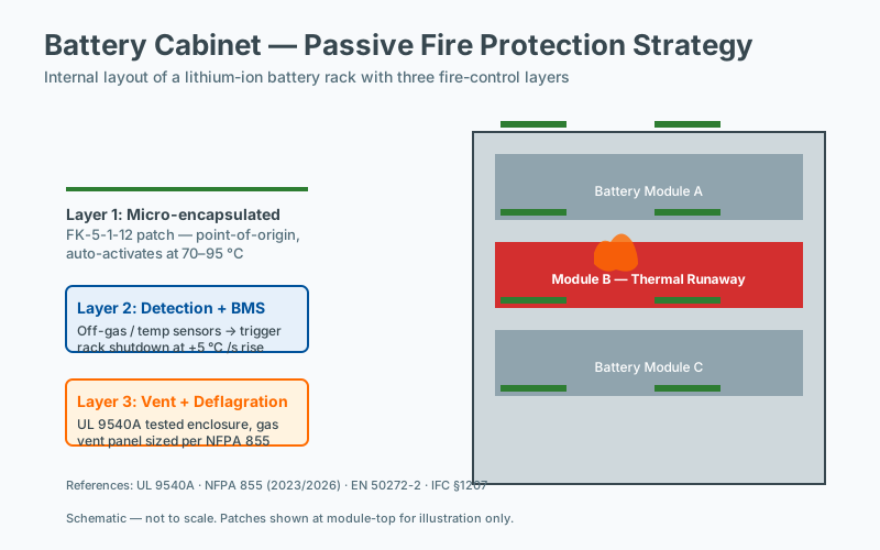
Suppression: water or water-mist suppression is the most effective agent for lithium-ion thermal runaway because water cools the cells and prevents propagation. Clean-agent gas systems alone are generally not considered adequate for lithium-ion rooms, although inert-gas systems can be used to suppress secondary fires in surrounding equipment. A growing number of installations also specify rack-level aerosol or clean-agent units inside individual battery cabinets to suppress a propagating event at its source.
2.4 Cable Trays and Pathways
Cable trays—both overhead and underfloor—are continuous fire pathways. A fire originating in one rack can travel along trays for tens of meters before being detected at room level. The principle here is to interrupt this pathway, not just to detect at its endpoints.
Detection: fiber-optic linear heat detection laid along the tray, or aspirating sampling points located at tray penetrations and junctions.
Suppression: fire-stop pillows, intumescent pillows, and rated cable-coating materials provide passive compartmentation. For active suppression, localized aerosol or condensed-aerosol generators can be placed at strategic points in the tray run to suppress a developing fire before it propagates.
2.5 Raised Floor vs. Overhead
The plenum beneath a raised floor is a particular concern. It typically contains:
- Power whips feeding racks
- Network and fiber cabling
- Sometimes service water piping for cooling
- Sometimes leak-detection cables
A fire under the floor can go undetected for an extended period if only ceiling-mounted detection is installed. Conversely, in a hot-aisle containment configuration, the overhead space may be more accessible to inspection but may also contain large volumes of warm, stratified air that masks the smoke signal.
Best practice:
- Provide both underfloor and overhead (ceiling-level) aspirating detection.
- Ensure that the underfloor ASD samples air returning from the racks, not air that has bypassed them.
- Specify firestopping at all underfloor penetrations between zones.
2.6 Ancillary Zones
Other zones—generator halls, fuel-storage rooms, loading docks, mechanical rooms containing chillers—are addressed by more conventional fire-protection practice but should be incorporated into the overall zone model so that detection and alarm signals are coordinated. A generator-day-tank fire, for example, should not result in a wholesale shutdown of the white space; conversely, a white-space event should not disable the fire pumps serving the generator hall.
3. The Multi-Layer Suppression Approach
A layered approach treats fire protection as a set of concentric, nested defenses. Each layer is sized to handle a specific failure mode and to buy time for the next layer to engage.
3.1 Layer 1 — Component-Level (Inside the Rack)
The innermost layer consists of component-level and enclosure-level protection. This includes:
- Self-extinguishing materials for cable jacketing (LSZH, IEC 60332-3 rated).
- Current-limiting fuses and circuit breakers coordinated to clear arcing faults quickly.
- Built-in over-temperature shutdown on power supplies.
- At the enclosure level, self-contained aerosol or clean-agent fire-suppression modules mounted inside the rack or cabinet. These units detect and suppress independently of the room-level system, using either linear heat cable, optical smoke sensing, or both.
This layer is often described as “passive suppression at the rack or enclosure level” because, once installed, it requires no human intervention and operates autonomously. Its role is to handle the incipient event before it escapes the rack.
3.2 Layer 2 — Row or Aisle-Level
Row-level containment uses aisle containment systems (curtains, doors, roofs) combined with per-row or per-aisle suppression modules. A row-level detection event can trigger a row-specific clean-agent discharge, isolating the affected row without disturbing the rest of the room.
This is increasingly common in hyperscale and colocation environments where high rack densities (15–30+ kW per rack) make room-level discharge undesirable for availability reasons.
3.3 Layer 3 — Room-Level
Room-level suppression remains the final line of defense and is required by most jurisdictional codes. The choice of agent and system type is governed by:
- The availability and integrity of the room envelope (for clean agents).
- The presence of occupants (clean agents typically require evacuation before discharge).
- The value and density of the IT load.
- Local code (e.g., NFPA 13 for sprinklers, NFPA 2001 for clean agents, NFPA 750 for water mist).
3.4 Layer 4 — Building-Level and External
Beyond the data center itself, the broader building fire-protection infrastructure—sprinklers in adjacent occupancies, fire pumps, alarm and mass-notification systems, smoke-management systems—provides the outermost defense.
4. NFPA 75 Requirements
NFPA 75 (Standard for the Fire Protection of Information Technology Equipment) is the principal North American standard for data center fire protection. The 2024 edition (with continuous revisions through 2026) places significant emphasis on:
- Detection sensitivity. NFPA 75 requires either spot-type smoke detection listed for the environment, air-sampling-type smoke detection, or both. Spot detectors must be listed for the air movement and temperature conditions of the space.
- Automatic sprinkler protection. Where sprinklers are installed, they must comply with NFPA 13. The standard explicitly allows the substitution of a non-water-based system for sprinklers only under specific conditions, including demonstrated room integrity for clean agents.
- Separation of IT equipment from other occupancies. The standard requires fire-rated separations between the IT space and adjacent spaces.
- Battery protection. The most recent editions of NFPA 75 contain detailed requirements for lithium-ion battery installations, including thermal runaway propagation testing (referencing UL 9540A) and minimum separation distances.
- Cable management. NFPA 75 requires that cabling under raised floors be neatly arranged and that abandoned cables be removed—a passive protection measure that reduces fuel load and improves airflow.
- Discharge planning. NFPA 75 requires a documented discharge plan that defines the conditions under which a clean-agent or sprinkler system will be manually delayed or disabled, and the criteria under which suppression must proceed without delay.
NFPA 75 should be read alongside NFPA 76 (Standard for the Fire Protection of Telecommunications Facilities), NFPA 855 (Standard for the Installation of Stationary Energy Storage Systems), and—where water mist is used—NFPA 750.
5. EN 50600 Framework
In Europe and many jurisdictions worldwide, the EN 50600 series (Information Technology — Data Centre Facilities and Infrastructures) provides a comprehensive framework. Although EN 50600 is not exclusively a fire-protection standard, its Class 4 environment and infrastructure clauses are tightly coupled with fire-safety expectations.
Key elements:
- EN 50600-2-4 (Telecommunications Cabling Infrastructure) includes provisions for fire performance of cabling.
- EN 50600-2-5 (Security Systems) addresses physical security, including the protection of fire-protection systems themselves from tampering or accidental activation.
- EN 50600-2-6 often supports the integration of environmental and safety monitoring.
The most relevant for fire strategy is the broader EN 50600-2-x family combined with the EN 50600-1 availability classes. A Class 4 data center must tolerate multiple concurrent failures of active systems; this requirement naturally extends to fire protection, and pushes operators toward the layered, zoned approach described above.
Where EN 50600 is in force, it is typically supplemented by:
- EN 54 series for fire detection and alarm.
- EN 13501-2 for fire-resistance ratings of construction elements.
- ISO 14520 and EN 15004 for gaseous extinguishing systems.
6. Detecting at the Rack Level Before Room-Level Activation
The objective of any layered design is that the innermost layer detects and suppresses first, with each outer layer acting as a fallback. This requires rack-level detection that is genuinely faster and more sensitive than room-level detection.
6.1 Detection Technologies Suited to the Rack
- Optical smoke sensing inside the rack. Miniaturized aspirating or point-type smoke sensors placed at the rack exhaust (typically the rear door or top of cabinet) detect smoke before it reaches the room.
- Thermal sensing. Linear heat detection or distributed temperature sensing (DTS) along power cables and bus bars.
- Gas sensing for lithium-ion. Off-gas detectors that sense electrolyte vapors (e.g., DMC, EMC, DEC) at concentrations orders of magnitude below flammable thresholds.
- Airflow and pressure sensing. Used as supporting indicators, not primary detection.
6.2 Avoiding False Discharge
The principal risk of rack-level detection is false positive—particularly nuisance alarms from dust, fiber breakage, or transient humidity. Best practices:
- Multi-criteria verification. Require coincidence between two different sensor types (e.g., smoke + thermal) before discharge.
- Pre-alarm escalation. Stage the response: a single-sensor event triggers a pre-alarm for investigation; a confirmed event triggers rack-level discharge; room-level discharge is reserved for events that escape the rack.
- Per-rack latching and reset. Each rack-level unit must be independently resettable to allow a contained event to be cleared without a full-room reset.
6.3 Coordination with Room-Level Systems
The BMS/EPMS must clearly differentiate between:
- Pre-alarms (informational, no shutdown).
- Rack-level alarms (load shed for that rack, suppression activation, optional load transfer).
- Aisle-level alarms (row shutdown, evacuation of the affected row).
- Room-level alarms (full room suppression, evacuation, utility isolation).
The hierarchy should be tested under controlled conditions and documented in the fire-incident response procedure.
7. Containment Strategies
Containment, both passive and active, is what prevents a fire from crossing zones.
7.1 Passive Containment
- Fire-rated construction. Walls, floors, and penetrations between zones rated per local code (commonly 1–2 hours).
- Firestopping at penetrations. Especially important where cable trays, conduit, and piping pass through fire-rated walls.
- Cable-coating materials. Intumescent coatings or fire-retardant wraps applied to cable bundles in critical pathways.
- Sealed raised-floor systems. Gasketed tiles and sealed penetrations prevent underfloor smoke from migrating across zones.
7.2 Active Containment
- Aisle containment systems. Hot-aisle or cold-aisle containment with automatic fire/smoke dampers in the air-handling system.
- Smoke-management systems. Coordinated with detection to pressurize adjacent zones and exhaust the affected zone.
- Fire dampers in ductwork. At all zone boundaries.
- Self-closing fire doors. At all zone access points.
7.3 Containment as an Enabler of Clean-Agent Discharge
A clean-agent room-level system is only effective if the room can be held at the design concentration for the required soak time. Containment is what makes this possible. A well-designed zone-based system treats the room envelope as a fire-rated container, with all penetrations firestopped and all doors self-closing and gasketed.
8. The Role of Passive Suppression at Individual Rack/Enclosure Level
Passive suppression—more accurately, self-contained active suppression—at the rack or enclosure level has emerged as a critical element of the layered strategy.
8.1 What It Is
A typical unit consists of:
- A detection element (smoke, thermal, or both).
- A small suppression agent reservoir (aerosol, clean gas, or—in some specialized applications—water mist).
- A triggering and control module, often with battery backup.
- A means of discharging the agent locally, inside the rack or cabinet.
The unit operates independently of the room-level system. On detection of a qualified event, it discharges its agent into the enclosure, suppressing the incipient fire and typically removing electrical power to the rack through an integrated relay.
8.2 What It Does
- Suppresses the incipient event. By the time a fire is detected at the rack, the event may already be at a stage where it would eventually trigger room-level detection. By intervening at this stage, the rack-level unit prevents the event from progressing further.
- Limits collateral damage. Suppression is confined to the rack. Adjacent racks, the room envelope, and the rest of the data center are unaffected.
- Maintains availability. A contained event does not result in a room-level shutdown. Service to other tenants or business units continues.
- Buys time for response. The room-level system stands by as a backup, while on-site or remote staff investigate.
8.3 Limitations
Rack-level suppression is not a substitute for room-level protection. It is intended to handle the common case of an incipient event inside a single enclosure. A fully developed fire, an event that has escaped the rack, or a battery thermal-runaway event that has propagated to multiple shelves will exceed the capacity of rack-level units. The room-level system remains essential.
8.4 Standards and Listings
Rack-level suppression units are typically listed or certified by independent testing laboratories. The applicable standards vary by jurisdiction and agent type, but operators should require documented third-party certification rather than relying solely on manufacturer claims.
9. Integration with the Building Management System
A zone-based, multi-layer strategy is only as effective as its integration. Key requirements:
- Single source of truth for alarm status. The BMS/EPMS should display, in real time, the status of every detector in every zone.
- Event-driven sequences of operation. Documented, tested sequences for each alarm scenario.
- Independent operation. Detection and suppression systems should not depend on the BMS for their core functions; the BMS is a notification and coordination layer.
- Logging and audit. Every detection event, every suppression discharge, every manual
Frequently Asked Questions
How does downtime risk factor into the fire protection decision?
Downtime cost often dominates the loss profile for industrial and data-center fires: equipment replacement is visible and bounded, but lost production or service is open-ended. A protection design that minimizes downtime (clean-agent, rapid activation, and minimal collateral damage) frequently has the strongest economic case even when its first cost is higher than alternatives.
What ROI can be expected from installing dedicated fire suppression?
ROI depends on the value at risk, the probability of an event, and the cost of the protection. For unmanned or remote enclosures with high-consequence equipment (battery cabinets, edge data, telecom), the avoided cost of a single incident often exceeds the lifetime cost of suppression many times over. Engineering ROI models typically combine expected loss reduction with insurance and regulatory benefits.
What is the minimum protection level recommended for this equipment type?
Minimum protection depends on the specific equipment and applicable standard; there is no universal answer. For the equipment type covered on this page, refer to the relevant NFPA, EN, UL, or GB document and to the equipment manufacturer's installation instructions. The protection level should match the consequence of loss, not the minimum the code allows.
Are there industry-specific guidelines beyond general fire codes?
Yes. Most industries have sector-specific guidance beyond the general fire code. Data centers follow NFPA 75 and NFPA 76 (now incorporated into NFPA 855 for ESS), telecom follows TIA standards, marine follows SOLAS and classification society rules, and energy storage follows NFPA 855 and UL 9540A. These sector documents typically take precedence over generic guidance for the same hazard.