Applications # Energy Storage Fire Protection Passive Fire Patch Editorial Team 2026-08-07 ## yaml title: “Energy Storage Fire Protection: Strategies for BESS Container and Cabinet Fire Risks” date: 2026-08-07
Battery Energy Storage Systems (BESS) have moved from experimental grid assets to critical infrastructure in less than a decade. Behind every solar farm, wind park, microgrid, and behind-the-meter commercial installation, racks of lithium-ion cells are now expected to deliver firm capacity, frequency response, and arbitrage revenue around the clock. That same ubiquity has exposed an uncomfortable truth: a grid-scale BESS container is one of the most energy-dense fire challenges ever deployed in routine commercial service, and the codes, products, and operational practices needed to protect them are still maturing.
This guide consolidates the engineering consensus on BESS fire protection for engineers, integrators, EPC contractors, AHJs (Authorities Having Jurisdiction), and facility managers. It covers the failure modes that initiate BESS fires, the layered protection model that the industry has converged on, the specific role of passive suppression patches, and the standards landscape that increasingly governs how these systems must be designed.
Why BESS Fires Are Different
A 40-foot BESS container can hold between 3 MWh and 5 MWh of usable energy depending on cell chemistry and configuration. That is the stored-energy equivalent of roughly 300 to 500 liters of gasoline, but it is packed into a footprint of about 30 m² — an energy density per unit area that no above-ground fuel storage facility would be permitted to approach. The implication is unavoidable: any thermal event inside a container has a far higher probability of becoming a catastrophic loss than a comparable event in conventional storage.
Several physical characteristics compound this risk:
- Cell proximity. Cells are packed as tightly as thermal management allows — typically 10–25 mm between cell walls — to maximize volumetric energy density. That spacing is also the conductive and convective pathway for thermal runaway propagation.
- Limited firefighting access. Container interiors are dense with busbars, coolant lines, BMS wiring, and module racks. Even when firefighters arrive promptly, they often cannot reach the seat of the fire without removing panels or risking electrical contact.
- Toxic and corrosive off-gases. Failing cells vent electrolyte vapors, hydrogen fluoride (HF), carbon monoxide (CO), hydrogen (H₂), and methane (CH�). HF in particular is hazardous at very low concentrations and complicates downwind evacuation decisions.
- Re-ignition and stranded energy. Lithium-ion cells can reignite hours, days, or — in documented cases — weeks after apparent extinguishment, because remaining charge in damaged cells continues to drive internal short circuits.
- Water reactivity. Although water mist is an effective cooling medium for Li-ion fires, applying large volumes of water onto exposed lithium can liberate hydrogen. The risk is bounded but real, and influences suppression-system design.
These factors explain why the fire-safety approach to BESS is fundamentally different from conventional electrical-room protection.
The BESS Failure Timeline
 Energy storage fire protection
Most documented BESS fires begin identically: an internal short circuit inside a single cell. The short can be triggered by manufacturing defects, mechanical damage during transport or installation, dendrite growth from cycling stress, thermal abuse, or progressive separator degradation. From that single-cell failure, a predictable sequence unfolds:
- T+0 s — Internal short. The separator between anode and cathode fails locally. Current bypasses the normal electrochemical path and heats the cell internally. The BMS may not detect this for tens of seconds because voltage and temperature excursions are still small.
- T+30–60 s — Off-gassing. The cell temperature climbs past the electrolyte boiling point. The cell vents a jet of hydrocarbon gases, CO, and HF precursors. This is the earliest detectable signal of impending thermal runaway.
- T+60–120 s — Thermal runaway. Exothermic reactions within the cell reach self-sustaining temperatures (typically 600–900 °c at the cell core). The cell ignites its own vent gases. Adjacent cells receive radiant and conductive heat.
- T+120–300 s — Module fire. Fire propagates cell-to-cell through the module. Busbars and plastic components contribute combustible loading. A single burning cell can drive its entire module into runaway within 2–5 minutes.
- T+5–15 min — Rack and container fire. Without intervention, the fire spreads to neighboring modules and racks. Smoke, heat, and pressure build inside the container. Blast relief panels (where fitted) vent the overpressure, but the fire is now firmly established.
- T+30 min+ — Propagation to adjacent containers. Radiant heat, ejected burning debris, and shared HVAC ducting can carry fire to neighboring containers. NFPA 855 spacing rules (typically 3 m / 10 ft between containers) are calibrated to reduce — but not eliminate — this risk.
The entire window for meaningful intervention is therefore about 3 to 5 minutes from first venting to module-level fire. Active container-level suppression typically cannot be deployed that quickly, and human firefighters almost never can. This is why engineers have looked to module-level passive suppression.
The Layered Protection Model
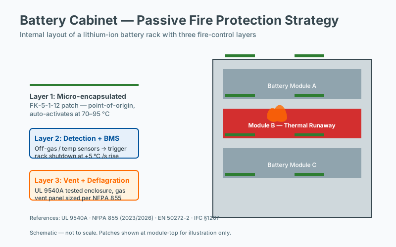
No single technology can mitigate all BESS fire risks. The industry consensus — codified in NFPA 855, UL 9540A, IEC 62933-5-2, and emerging CEN/TS standards — is a five-layer defense-in-depth model.
Layer 1: Prevention — Battery Management System (BMS)
The BMS is the first line of defense. Modern BMS architectures monitor cell-level voltage, current, and temperature with millisecond resolution. They track state-of-charge (SOC) and state-of-health (SOH), apply charge-balancing across cells, and disconnect modules or entire racks when anomalous conditions are detected. UL 1973 and IEC 62619 set the baseline functional and safety requirements for cells and BMS in stationary applications.
The goal of Layer 1 is prevention: stop thermal runaway from ever starting. A well-configured BMS catches overcharge, over-discharge, excessive C-rate, and overtemperature conditions before they cascade. It cannot, however, detect every internal short — particularly the dendrite-driven failures that develop silently over months.
Layer 2: Early Detection
Detection systems supplement the BMS by sensing the chemical signatures of cell venting before ignition. The most widely deployed technologies include:
- Off-gas (electrochemical) detection. Calibrated to HF, CO, H₂, or VOC signatures specific to the cell chemistry. Detection thresholds as low as 1–10 ppm are achievable.
- Acoustic emission sensing. Detects the micro-cracking sounds of separator failure inside the cell.
- Distributed temperature sensing (DTS). Fiber-optic cables routed through the rack provide continuous temperature profiles at sub-meter resolution.
- Smoke and heat detection. Standard aspirating smoke detection (ASD) inside the container, with cross-zoning to suppress false alarms.
Detection systems feed into the fire alarm control panel and, ideally, into the BMS to trigger automatic load shedding or module isolation.
Layer 3: Passive Module-Level Suppression
This is the layer where passive fire patches play their unique role. A passive fire patch is a self-contained, thermally activated suppression element — typically a composite of intumescent materials, endothermic fillers, and ablative fibers — that is mounted directly on the battery module or rack. When the surrounding air temperature reaches the activation threshold (commonly 150–170 °C), the patch deploys automatically, without any external power, signal, or moving parts.
The patch reacts by:
- Releasing cooling vapors that absorb heat endothermically.
- Expanding into a barrier that physically blocks radiant heat transfer to neighboring cells.
- Producing inert gas locally that suppresses flame propagation.
Because activation is purely thermal, the patch functions even when the BMS has failed, the container has lost power, and detection systems are offline. It acts on the cell or module that is already in runaway — the exact scenario that Layers 1 and 2 cannot prevent.
The goal of Layer 3 is containment: hold the fire at the module level for the minutes required for active systems or firefighters to respond, and prevent propagation to the rest of the rack.
Layer 4: Active Container-Level Suppression
Active suppression handles the scenario where a fire has escaped the module. Water mist is the predominant choice for outdoor and indoor BESS, with high-pressure (~40–80 bar) or low-pressure (~10 bar) configurations. Water mist cools the container interior and surrounding modules, displaces oxygen locally, and reduces radiant heat flux. Some installations use clean agent systems (Novec 1230, FM-200) for indoor cabinets, but these are less common at the container scale because of agent quantity and post-discharge ventilation challenges.
UL 9540A test data informs the design of the active system by establishing the maximum single-module heat release and the gas composition produced, which in turn drive nozzle count, flow rate, and discharge duration.
Layer 5: Containment and Spacing
The outermost layer addresses the failure mode where the container is lost: preventing fire from spreading to neighbors. Measures include:
- Fire-rated container construction (typically 1–2 hour ratings per UL/ULC standards).
- Spacing between containers — NFPA 855 mandates a minimum of 3 m (10 ft) between outdoor non-walk-in BESS units unless fire-resistant construction or supplemental suppression justifies a reduction.
- Blast relief panels to manage deflagration pressure from gas accumulation.
- Defendable perimeter access for fire department operations.
- Site-wide water supply sized for the largest credible event.
Containment is also where insurance carriers, such as those following FM Global Property Loss Prevention Data Sheet 5-33, exert significant influence on design.
Standards and Codes Governing BESS Fire Protection
A growing body of standards now governs how BESS must be designed, tested, and installed. Engineers should treat the following as the working baseline in 2026:
- NFPA 855 (Standard for the Installation of Stationary Energy Storage Systems) — U.S. installation requirements, including spacing, fire suppression, ventilation, and explosion protection.
- UL 9540 (Energy Storage Systems and Equipment) — System-level safety standard.
- UL 9540A (Test Method for Evaluating Thermal Runaway Fire Propagation) — The foundational test that characterizes whether a BESS design will propagate fire cell-to-cell, module-to-module, or unit-to-unit.
- NFPA 1 (Fire Code) and NFPA 101 (Life Safety Code) — Adopted in many jurisdictions and integrated with NFPA 855.
- IEC 62933-5-2 — International safety requirements for grid-integrated BESS.
- IEC 62619 — Secondary lithium cells for stationary applications.
- UN 38.3 — Transport testing for lithium batteries.
- FM Global DS 5-33 — Property loss prevention guidance for lithium-ion BESS.
- UL 1973 — Cells and BMS for stationary applications.
UL 9540A is the single most important document in the design chain. Its results — particularly the level of propagation observed (cell-to-cell, module-to-module, unit-to-unit, or installation-level) — drive suppression-system sizing, spacing decisions, and ultimately whether a given BESS design can be installed at a specific site.
Deployment Recommendations by BESS Class
The number, location, and mounting configuration of passive fire patches depend on the BESS class. General guidance:
| BESS Class | Typical Energy | Patch Deployment |
|---|---|---|
| Residential (5–20 kWh) | Wall-mounted or floor-standing cabinet | 1–2 patches at top of enclosure near cell stack |
| Commercial / Industrial cabinet (50–200 kWh) | Indoor or outdoor cabinet | 1 patch per rack (typically 3–6 racks) |
| Container (1–5 MWh) | 20-ft or 40-ft ISO container | 1 patch per module/rack + 1 at DC bus / inverter area |
| Open-air rack (utility scale) | Multiple containers at a site | 1 patch per module, weather-protected housing |
For containerized systems, patches should be sited at the upper third of each module where heat plumes accumulate, and additional patches are recommended at busbar and inverter enclosures where electrical fire risk is independent of cell-level events.
Cost-Effectiveness
A single 40-foot BESS container typically represents $300,000–$800,000 in asset value, depending on chemistry and inverter configuration. Fully equipping that container with passive patches on every rack costs approximately $2,000–$5,000 — on the order of 0.5–1% of asset value. When a single thermal runaway incident can destroy the entire container, damage adjacent units, and trigger extended site downtime, the cost case for module-level passive suppression is strong, even before considering insurance premium reductions and regulatory compliance benefits.
Operational and Maintenance Considerations
Passive fire patches require no external power, signal, or routine inspection beyond periodic visual checks. However, lifecycle management should include:
- Periodic thermal imaging during scheduled maintenance to verify patches are intact and unobstructed.
- Replacement after activation. Activated patches have consumed their reactive material and must be replaced before the system returns to service.
- Documentation in the BESS safety file for AHJ and insurer review.
Because patches are passive, they do not require annual recertification the way active suppression systems do, but they should be inventoried and tracked alongside other consumable safety items.
Future Directions
Several technology developments are reshaping the BESS protection picture:
- Sodium-ion and other alternative chemistries are entering the grid market, with different abuse characteristics and potentially slower propagation.
- Solid-state electrolytes promise to reduce or eliminate flammable liquid electrolyte, though the technology is not yet deployed at grid scale.
- Cell-to-pack and cell-to-chassis designs reduce module boundaries but introduce new propagation pathways.
- AI-driven BMS and predictive analytics aim to forecast cell failure hours or days in advance, shifting protection upstream.
Passive suppression remains relevant across all these scenarios because it addresses the worst-case event where upstream prevention has failed.
Frequently Asked Questions
Does passive suppression work for LFP as well as NMC batteries?
Both LFP (lithium iron phosphate) and NMC (nickel manganese cobalt) chemistries can undergo thermal runaway, though LFP typically releases less energy per cell and may not propagate as readily as NMC. Standards such as UL 1973 and IEC 62619 treat both chemistries as requiring propagation prevention, and UL 9540A is applied at the cabinet level regardless of chemistry. Suppression device selection should be based on the tested propagation behavior of the specific cabinet configuration rather than chemistry alone.
Can a fire in one battery cell spread to adjacent cells?
Yes. Once a cell enters thermal runaway, vented gas and radiant heat can propagate failure to neighboring cells within seconds to minutes, depending on cell spacing, state of charge, and module geometry. UL 9540A testing characterizes this propagation behavior at the cabinet level, and NFPA 855 treats propagation prevention as a primary design objective for stationary energy storage. Physical separation, thermal barriers, and suppression devices are commonly combined to interrupt the propagation chain.
What gas sensors detect early battery failure?
Early battery failure is typically detected through off-gas sensors that respond to the electrolyte vapor vented during the early stages of thermal runaway, well before cell temperature rises measurably. Commonly monitored species include hydrogen, carbon monoxide, and certain volatile organic compounds specific to the cell chemistry. Sensor placement inside the enclosure and a response threshold well below thermal-runaway temperature are required for the warning to be acted upon before propagation occurs.
What temperature triggers thermal runaway in Li-ion batteries?
There is no single thermal-runaway temperature for Li-ion cells; onset varies with chemistry, state of charge, age, and abuse condition. For most commercial cells, runaway onset typically occurs somewhere between 80 and 200 degrees Celsius, with self-sustaining exothermic reactions well above 150 degrees. Standards such as UL 9540A and IEC 62619 specify abuse tests rather than a single threshold, and suppression devices are designed to act before runaway onset is complete.