Applications # Ev Charging Station Fire Safety Passive Fire Patch Editorial Team 2026-08-07 ## yaml title: “EV Charging Station Fire Safety: Passive Protection for Charging Infrastructure” date: 2026-08-07 description: “Comprehensive technical analysis of fire risks in EV charging infrastructure — wallboxes, DC fast chargers, ultra-fast hubs — and how passive fire suppression provides reliable, always-on protection for distributed, often unattended charging networks.” author: “Passive Fire Patch Editorial Team” publisher: “Passive Fire Patch”
Introduction: A New Fire Risk Profile for a New Energy Network
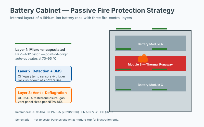 Battery-cabinet strategy applied to EV charging
Electric vehicle adoption is reshaping transportation, and with it, the physical infrastructure that supports it. By 2026, global EV charging deployments have crossed well into the tens of millions of ports, ranging from small residential wallboxes to utility-scale charging plazas delivering megawatt-class loads. While much of the public discourse focuses on range anxiety and grid impact, a quieter and more operationally significant concern has emerged: the fire safety of the charging equipment itself.
Charging stations — particularly high-power DC fast chargers and ultra-fast charging hubs — concentrate substantial electrical energy within compact enclosures that are frequently installed in exposed outdoor environments. Unlike traditional electrical infrastructure, charging stations are commonly unattended, lack fixed fire suppression plumbing, and are often sited far from emergency responders. Passive fire suppression technologies, particularly sealed chemical patches that activate autonomously when ambient temperature crosses a defined threshold, are uniquely suited to mitigate these risks.
This article examines the fire risk profile of EV charging infrastructure, categorizes failure modes observed in real-world incidents, and explains how passive suppression technology can be integrated into chargers at the OEM level or retrofitted into existing deployments.
What Makes EV Chargers a Fire Risk?
EV chargers are not simply electrical outlets. They are power conversion systems — increasingly sophisticated assemblies of silicon, copper, coolant, and control firmware. Several characteristics make them distinct from conventional electrical infrastructure:
Risk FactorDescriptionHigh power densityDC fast chargers deliver 50–350 kW through densely packed power electronics in compact cabinets, often exceeding 1 kW per liter of enclosure volume.Continuous operationPublic chargers operate 24/7, often at sustained high load, with minimal cool-down periods.Outdoor exposureHeat, humidity, UV radiation, dust ingress, and thermal cycling stress components and degrade insulation over time.Connector wearRepeated mating cycles degrade contact surfaces, increasing contact resistance and localized heating.Cable damageCharging cables are routinely run over, pinched, kinked, or improperly stowed by users.Vandalism and impactPublic chargers in parking structures, rest stops, and curbside locations face physical abuse and vehicle impacts.Vehicle-side faultsA fault within the connected vehicle’s battery management system can propagate current anomalies upstream into the charger.Software faultsFirmware bugs, communication errors, or failed firmware updates can leave chargers in undefined operating states.
Standards bodies have begun addressing this risk profile. NFPA 70 (National Electrical Code) Article 625 covers EV charging equipment, while IEC 61851-1 and the newer IEC 61851-23 series define safety requirements for conductive charging systems, including overcurrent protection, insulation monitoring, and thermal management. EN 61851-23 applies the equivalent requirements in the European market. UL 2202 and UL 2594 address stationary charging equipment in North America. While these standards mandate robust electrical protection, they do not — at present — require on-board fire suppression within charger enclosures, leaving a gap that passive technology can fill.
Types of Charging Infrastructure and Their Risk Profiles
Level 2 AC Chargers (Wallboxes)
Power range: 3.7–22 kW Typical enclosure: Compact wall-mounted unit, typically 5–30 liters internal volume Risk profile: Low to moderate. Lower power means lower fault energy, but the units are widely deployed in residential garages and multifamily buildings where fire spread can have severe consequences. Suppression approach: A single compact patch mounted above the power electronics board is generally sufficient. Wallbox enclosures are small enough that a single suppression source can flood the internal volume effectively.
DC Fast Chargers (50–150 kW)
Power range: 50–150 kW Typical enclosure: Floor-standing cabinet with internal volume of approximately 1.5–3 m³ Risk profile: Medium. Power modules — typically insulated-gate bipolar transistor (IGBT) or silicon carbide (SiC) MOSFET-based converters — generate significant waste heat. Liquid cooling loops carry dielectric coolant through cold plates bonded to switching devices. Suppression approach: Two to three suppression patches distributed across the upper region of each power module bay, positioned to flood the volume above heat-generating components.
Ultra-Fast Chargers (150–350 kW)
Power range: 150–350 kW, with some systems now approaching 400–600 kW Typical enclosure: Large cabinet, often with a separate power cabinet feeding one or more dispenser units Risk profile: Medium to high. Multiple paralleled power modules share load but also concentrate fault potential. Active liquid cooling systems introduce leak risks and pump failures. Suppression approach: Three to four patches per power cabinet, with additional coverage in dispenser units where DC contactors and cable terminations reside.
Charging Hubs and Depots
Architecture: Centralized power conversion cabinets with DC bus distribution to multiple dispensers; battery-buffered stations with on-site energy storage; depot charging for commercial fleets. Risk profile: Highest. Concentrated power capacity, complex inter-cabinet cabling, often co-located with battery energy storage systems (BESS) that may themselves present thermal runaway risk. Suppression approach: Patches installed in every power module cabinet, every dispenser, and — where applicable — within or adjacent to on-site storage enclosures. Coordinated coverage planning is essential.
Documented Fire Failure Modes in EV Chargers
Real-world incident data, drawn from public fire investigation reports, manufacturer recalls, and insurance loss adjusters, reveals recurring failure patterns:
Power module semiconductor failure — Short-circuit events in IGBTs or MOSFETs produce rapid localized heating that can exceed 600 °C within seconds, igniting adjacent PCB substrates, busbar insulation, and plastic housings.
Loose electrical connections — High-resistance joints at terminal blocks, busbar bolted connections, or DC output studs generate sustained heating under load. These faults often develop gradually before reaching ignition temperature.
Contactor welding — Mechanical contactors that fail to open when commanded become stuck in the closed position, allowing uncontrolled current flow into the vehicle or downstream cabling.
Cooling system failure — Leak of dielectric coolant from fittings, hoses, or cold plates eliminates heat extraction from semiconductors. Temperature rises rapidly, and fault detection may not occur before thermal damage is sustained.
Vehicle-originating faults — A battery pack entering thermal runaway while connected to a charger can produce extreme heat and flammable gas venting that exposes the charger’s dispenser and cable to direct flame impingement.
Environmental and biological factors — Rodent damage to wiring harnesses, insect ingress into ventilation openings, water intrusion through degraded gaskets, and corrosion of outdoor connectors are all documented contributors.
Cable management failures — Improperly stowed cables subjected to repeated flexing or crushing develop internal conductor breaks that arc under load.
These failure modes share a common characteristic: they typically begin as electrical anomalies that transition to thermal events, and from thermal events to flaming combustion, faster than external emergency response can intervene.
Why Passive Suppression Fits Charging Infrastructure
Always-On, Unattended Operation
EV chargers are routinely installed in locations without on-site staff — public parking lots, highway rest stops, municipal curbsides, residential streets, and remote fleet depots. There is often no alarm monitoring, no regular inspection cadence, and no personnel trained to respond to a developing fire. A suppression system that activates only on alarm signal is of limited value when there is no one to hear the alarm.
Passive suppression patches operate independently of any external signal. They contain a sealed chemical agent that releases automatically when the ambient temperature at the patch surface crosses the activation threshold — typically 170 °C or 200 °C depending on formulation. From the moment of installation, the charger is protected 24/7, indefinitely, with zero human intervention required.
No External Infrastructure Required
Water-based suppression systems require a piped water supply, adequate pressure, drainage, and often a dedicated pump house or connection to municipal supply. Gaseous systems require a room integrity test, pressure relief paths, and in many jurisdictions, dedicated breathing apparatus for personnel re-entry. None of these prerequisites exist at most charger locations.
A passive patch requires none of this. It is a self-contained device that fits inside a charger cabinet during assembly or as a retrofit. Installation typically takes only minutes and requires no modification to the charger’s electrical system.
Weather and Temperature Resilience
Chargers installed in Nordic climates, northern North America, or high-altitude locations may experience ambient temperatures well below −30 °C in winter. Water-based suppression systems risk freezing and loss of function. Clean agent suppression systems using FK-5-1-12 (Novec 1230) or HFC-227ea remain functional across an extreme temperature range, and the sealed patch construction prevents moisture ingress or agent loss over a multi-year service life.
Retrofit Compatibility
The existing global fleet of chargers numbers in the millions and continues to grow. Operators cannot replace functional equipment merely to add fire suppression. Passive patches are specifically designed to be installed into existing enclosures without disconnecting or modifying the electrical system — a critical advantage for networks with thousands of dispersed assets.
Minimal Maintenance Burden
Periodic inspection of charger enclosures is already part of most operators’ preventive maintenance programs. Adding visual inspection of suppression patches to that workflow introduces minimal additional cost. The patches themselves have multi-year service lives — typically five to ten years depending on environmental exposure — and can be replaced individually as part of routine maintenance cycles.
Installation Best Practices
Patch placement within a charger enclosure significantly affects suppression effectiveness. Best practice guidelines, derived from both laboratory testing and field experience, include:
LocationActivation TemperatureRationaleAbove power electronics board (wallbox)170 °CHeat rises; electronics are the most probable ignition sourceAbove each power module (DC fast charger)170 °C, or 200 °C if adjacent to a heat sinkCaptures semiconductor and PCB fires at originTop of power cabinet near busbar connections170 °CBusbar joints are a documented failure pointAbove cable termination points170 °CTermination resistance faults develop hereAdjacent to liquid cooling manifolds170 °CCoolant leaks create hot spots and reduce cooling capacity
Multiple patches should be used where the internal volume or geometry of the enclosure prevents a single source from providing uniform coverage. The agent discharge pattern — typically a radial or fan-shaped dispersion — must reach the most probable ignition sources within the activation-to-flood time, which for the most common agents is on the order of 5–15 seconds.
Standards Context and Regulatory Direction
Several standards are relevant to fire safety in EV charging equipment, though none currently mandate on-board suppression:
- NFPA 70 Article 625 — National Electrical Code requirements for EV charging equipment, including overcurrent protection, disconnecting means, and ventilation.
- IEC 61851-1 / IEC 61851-23 — International standards for conductive charging systems, addressing safety and communications.
- UL 2202 / UL 2594 — Standards for stationary EV charging equipment in North America.
- NFPA 855 — Standard for the installation of stationary energy storage systems; relevant where chargers are co-located with BESS.
- EN 50575 / CPR — Construction Products Regulation requirements for cables used in fixed installations.
- ISO 17840 — Reference standard for vehicle and equipment rescue sheets, increasingly used to communicate hazards to first responders.
Insurance carriers and code authorities are paying increasing attention to charger fire incidents, and it is plausible that future revisions of IEC 61851-23 or NFPA 70 will incorporate explicit fire suppression requirements for certain charger categories, particularly those co-located with occupied buildings or high-traffic public spaces.
Cost-Benefit Analysis for Charging Operators
A typical DC fast charger represents a capital investment of $20,000–$50,000 for the equipment alone, with total installed costs including site preparation, electrical service, and commissioning often reaching $80,000–$150,000. A fire that destroys the charger typically damages or destroys the connected vehicle as well — a $30,000–$100,000 additional loss — and may damage adjacent chargers, vehicles, or structures.
Beyond direct property loss, operators face consequential costs: site downtime, network availability degradation, customer churn, regulatory scrutiny, and potential liability exposure if fire spread affects third parties.
Adding passive fire suppression costs approximately $100–$300 per charger in material, plus installation labor. For a network of 100 chargers, the total investment is $10,000–$30,000 — a marginal fraction of the asset value being protected. The cost-benefit case is straightforward: suppression expenditure representing 0.5–1% of equipment value, mitigating risk of loss events that can exceed the entire network’s capital cost.
For OEM integrators, the incremental bill-of-materials cost is similarly modest, while the differentiation value — particularly in competitive public procurement contexts where safety is weighted — can be significant.
Frequently Asked Questions
Are there industry-specific guidelines beyond general fire codes?
Yes. Most industries have sector-specific guidance beyond the general fire code. Data centers follow NFPA 75 and NFPA 76 (now incorporated into NFPA 855 for ESS), telecom follows TIA standards, marine follows SOLAS and classification society rules, and energy storage follows NFPA 855 and UL 9540A. These sector documents typically take precedence over generic guidance for the same hazard.
What makes this application different from general fire protection?
Each application has specific constraints: enclosure volume, fire load, ventilation, agent compatibility, downtime tolerance, and applicable standards. The differences are not always obvious: a battery cabinet and a server rack have very different fire loads and suppression agent requirements despite both being electronics enclosures. The application pages in this site describe these constraints in detail.
How does downtime risk factor into the fire protection decision?
Downtime cost often dominates the loss profile for industrial and data-center fires: equipment replacement is visible and bounded, but lost production or service is open-ended. A protection design that minimizes downtime (clean-agent, rapid activation, and minimal collateral damage) frequently has the strongest economic case even when its first cost is higher than alternatives.
What ROI can be expected from installing dedicated fire suppression?
ROI depends on the value at risk, the probability of an event, and the cost of the protection. For unmanned or remote enclosures with high-consequence equipment (battery cabinets, edge data, telecom), the avoided cost of a single incident often exceeds the lifetime cost of suppression many times over. Engineering ROI models typically combine expected loss reduction with insurance and regulatory benefits.