Fire Science # ‘Flash Point vs. Auto-Ignition Temperature: Understanding Fire Thresholds’ Passive Fire Patch Editorial Team 2026-08-07 ## Executive Summary
Fire incidents in chemical plants, refineries, fuel terminals, and battery energy storage systems rarely begin with a dramatic explosion. More often, they originate from a subtle thermal event: a slowly leaking valve, a warm bearing, a hot surface in contact with a hydrocarbon mist. To design against such hazards, engineers must speak a precise vocabulary about fire thresholds — the temperatures at which a substance transitions from a passive liquid to a self-propagating flame.
Three thermal properties dominate this vocabulary:
- Flash Point (FP) — the lowest temperature at which a liquid emits enough vapor to form an ignitable mixture with air near its surface.
- Fire Point — the lowest temperature at which that mixture supports sustained combustion for at least five seconds.
- Auto-Ignition Temperature (AIT) — the lowest temperature at which the substance ignites spontaneously, without any external pilot flame.
Misreading these values, or conflating one with another, has led to real-world disasters. This article provides a rigorous, vendor-neutral reference for engineers, EHS professionals, laboratory technicians, and technical writers who need to apply these concepts in specification documents, P&IDs, hazardous area drawings, and risk assessments.
1. Definitions and Conceptual Framework
 Thermal threshold diagram
1.1 Flash Point
The flash point is the lowest liquid temperature, corrected to standard atmospheric pressure (101.325 kPa), at which application of a standardized ignition source causes the vapor-air mixture above the liquid surface to ignite — but not sustain combustion. The phenomenon is governed by vapor pressure kinetics: as temperature rises, more molecules escape the liquid phase. Once the vapor concentration crosses the lower flammable limit (LFL), the mixture becomes thermodynamically capable of a flame propagation front, provided a small activation energy is supplied.
Crucially, flash point does not mean the liquid will burn continuously. After the brief flash, the surface cools slightly (due to vaporization), and the flame extinguishes unless additional heat is supplied.
1.2 Fire Point
The fire point is typically 5 °C to 20 °C higher than the flash point. It is the temperature at which the liquid emits vapor fast enough that, once ignited by a pilot, combustion persists for at least five seconds after the pilot is removed. The fire point matters because it represents the boundary between a transient flash and a sustainable pool fire.
In many safety codes, fire point is implicitly used when regulations speak of “liquids that will support combustion” — particularly for Class IIIB liquids (flash point ≥ 93.3 °C / 200 °F) under NFPA 30, where the fire point is sometimes the controlling parameter for insurance and storage rules.
1.3 Auto-Ignition Temperature (AIT)
The auto-ignition temperature (also written as autoignition temperature, and sometimes called spontaneous ignition temperature or SIT) is the minimum temperature at which a substance ignites without any external flame, spark, or pilot. AIT is governed by radical chain-branching kinetics: as the bulk temperature rises, the rate of homolytic bond cleavage in fuel molecules accelerates exponentially (per Arrhenius kinetics). When the rate of radical generation exceeds the rate of radical termination, a thermal runaway to ignition occurs — typically within 0.1 to 10 seconds.
AIT values are substantially higher than flash points. For example, n-hexane has a flash point near −22 °C but an AIT of about 225 °C. This 250-degree gap defines the engineering margin that separates “needs a spark” from “will catch fire on a hot pipe.”
1.4 The Three Zones of Thermal Hazard
A useful mental model divides the temperature scale into three regimes:
RegimeThermal ConditionHazard BehaviorBelow Flash PointCooler than FPLiquid too cold to release flammable vapor; ignition impossible without forced atomizationBetween FP and AITVapor ignitable if pilotedNeeds a spark or flame; passive heating alone is insufficientAbove AITHotter than AITSpontaneous ignition; no ignition source required
This three-zone framework is the foundation of all hazardous area classification work, including ATEX, IECEx, NEC 500/505, and the Canadian CEC.
2. Physical Chemistry Behind Each Threshold
2.1 Flash Point as a Vapor-Pressure Equilibrium
The flash point corresponds closely to the temperature at which the liquid’s saturation vapor pressure produces a vapor concentration equal to the lower flammable limit (LFL). For many hydrocarbons, this relationship is approximated by:
$$P_{sat}(T_{FP}) \approx \frac{LFL \cdot P_{atm}}{100}$$
where $P_{sat}$ is the saturation vapor pressure at the flash point temperature, and LFL is expressed in volume percent. Because vapor pressure rises roughly exponentially with temperature, a small change in temperature produces a measurable change in flammability — which is why flash points must be measured under strict thermal equilibrium conditions.
2.2 Fire Point and Sustained Heat Release
Once a piloted flash occurs, the question is whether the heat feedback from the flame (radiation + conduction back to the liquid) is sufficient to vaporize additional fuel at the rate required to maintain the flame. The fire point represents the temperature at which the heat flux from the flame equals or exceeds the heat losses to the surroundings and to vaporization. This is why fire points depend on sample size, container geometry, and ambient air movement — a subtle but important reason why closed-cup testers (which limit air movement) yield slightly different values from open-cup testers.
2.3 Auto-Ignition as Kinetic Runaway
AIT is fundamentally different: it is a chemical kinetics phenomenon rather than a thermodynamic equilibrium. The Semenov model of thermal ignition treats the system as a continuously heated volume where heat generation from exothermic oxidation follows an Arrhenius law, while heat loss follows Newton’s law of cooling:
$$\rho c V \frac{dT}{dt} = Q , Z , e^{-E_a/RT} - h S (T - T_0)$$
When the Frank-Kamenetskii parameter $\delta$ exceeds a critical value that depends on geometry (slab, cylinder, sphere), the system experiences thermal runaway. This is why AIT can decrease dramatically in large volumes or with long residence times — a critical fact for design of oven curing, drying tunnels, and compressor crankcases.
3. Standardized Test Methods
Test results must always be reported with their method code. A flash point of “62 °C” without a method is ambiguous; “62 °C (ASTM D93, Procedure B)” is unambiguous.
3.1 ASTM D56 — Tag Closed Cup
- Apparatus: Tag closed-cup tester.
- Sample size: ~50 mL.
- Application: Liquids with FP below 93 °C (200 °F) — primarily petroleum distillates, solvents, and cut-back bitumens.
- Principle: Sample is heated in a sealed brass cup with a slow stir; at specified temperature intervals, a small flame is inserted through an opening.
- Merits: Fast, low-cost, widely used in petroleum QC.
- Limitations: Sensitive to ambient drafts; less reproducible for very volatile fluids.
3.2 ASTM D93 — Pensky-Martens Closed Cup
- Apparatus: Pensky-Martens tester with motorized stirrer.
- Procedure A: For ambient heating to FP below 40 °C.
- Procedure B: For samples with expected FP ≥ 40 °C up to 360 °C (typical for diesel, lube oils, biodiesel blends).
- Sample size: ~75 mL.
- Application: The default method in most lubricant and fuel specifications; cited in EN 22719, ISO 2719, IP 34, and many petroleum standards.
- Merits: Excellent reproducibility across a broad range; integrated stirrer reduces operator variability.
3.3 ASTM D92 — Cleveland Open Cup
- Apparatus: Open brass cup, no lid.
- Application: Determination of fire point and flash point for petroleum products and lubricants with FP above 79 °C (175 °F).
- Merits: Open-cup fire point is more representative of spill and pool fire scenarios.
- Limitations: Open to atmosphere — not safe for highly volatile samples.
3.4 ASTM E659 — Auto-Ignition Temperature of Liquid Chemicals
- Apparatus: A uniformly heated 500 mL borosilicate flask, a thermocouple in the vapor phase, and a syringe injection system.
- Procedure: Air is preheated to a set temperature, then a fixed volume (typically 0.10–0.20 mL) of the test substance is injected. Ignition is observed visually or via thermocouple excursion.
- Intervals: Tested at 3 °C intervals to bracket the AIT; the lowest temperature at which ignition occurs is reported.
- Limitations: AIT is highly volume- and time-dependent. ASTM E659 results typically represent a 0.5 s delay time in a 500 mL flask. Values in large heated vessels or process equipment can be 50–100 °C lower.
3.5 Other Standards Worth Knowing
StandardScopeRegionISO 2719Equivalent to ASTM D93InternationalEN 22719Closed-cup, Pensky-Martens equivalentEuropeIP 34 / IP 35UK petroleum institute methodsUK / CommonwealthDIN 51758German method (Setaflash)GermanyGB/T 261Chinese national equivalent of D93ChinaJIS K 2265Japanese flash point standardsJapan
3.6 Closed Cup vs. Open Cup: A Practical Note
Closed-cup testers (D56, D93) yield flash points that are typically 2–8 °C lower than open-cup testers (D92, D1310) for the same liquid. This is because the closed lid saturates the headspace with vapor. For regulatory documents, you must declare which method was used. For risk assessment, the lower (closed-cup) value is generally the conservative choice.
4. Hazardous Area Classification
Fire thresholds translate directly into explosion protection zones. The logic flows from the flash point and vapor density of the process fluid.
4.1 ATEX / IECEx Zone System (IEC 60079-10)
ZoneDefinitionTypical SourceZone 0Flammable atmosphere present continuously or for long periodsInside a process vessel, closed-top tank ventZone 1Likely to occur in normal operationFlanges, pump seals, sample points near liquids above FPZone 2Not likely in normal operation, and if it does, persists only brieflySecondary containment, around sealed equipment
A liquid above its flash point that is handled in open equipment is the classic Zone 1 source. A liquid handled well below its flash point but with occasional releases can be Zone 2.
4.2 NEC Class / Division System (US)
ClassHazard TypeClass IFlammable vapors or gasesClass IICombustible dustsClass IIIIgnitable fibers/flyings
DivisionFrequencyDivision 1Normal operationDivision 2Abnormal conditions
For Class I, the dividing line between Division 1 and Division 2 is essentially the same conceptual threshold as ATEX Zone 1 vs. Zone 2 — the difference is gas groups (A: acetylene, B: hydrogen, C: ethylene, D: propane) and historical convention.
4.3 Temperature (T) Codes
After the zone is determined, equipment surfaces must be limited to temperatures below 80% of the AIT (per IEC 60079-0) or below the ignition temperature of the specific gas (per NEC 500). Common T-ratings:
T-CodeMax Surface TempTypical GasesT1450 °CHydrogen, methane, propaneT2300 °CEthyleneT3200 °CAcetone, many solventsT4135 °CDiethyl ether, ethyl alcoholT5100 °C— (rare)T685 °CCarbon disulfide
Example: Diesel has an AIT around 210–250 °C. Electric motors in a diesel-handling area must therefore carry a T3 (≤ 200 °C) rating or lower to satisfy the 80% safety factor.
5. Practical Significance for Equipment and Material Design
5.1 Electric Motor and Drive Selection
An explosion-proof motor is not enough — the surface temperature of the motor windings, bearings, and terminal boxes must be below the AIT of the most easily ignitable gas in the area. A common mistake is to install T4-rated motors (135 °C) in an atmosphere containing a solvent with AIT of 180 °C. While T4 might seem acceptable, if the actual motor surface runs at 130 °C under full load in a 50 °C ambient, the 80% margin may be insufficient; you must verify the temperature class of the specific atmosphere group, not just the equipment T-code.
5.2 Heating Systems and Tracing
Heat tracing of pipelines carrying combustible fluids must:
- Be designed so that maximum sheath temperature is at least 20 °C below the AIT of the fluid in air.
- Account for worst-case ambient temperature plus thermostat failure (typically +20 °C safety margin).
- Avoid dead legs and stagnant sections where localized heating can elevate fluid above its flash point.
5.3 Materials of Construction
Material selection is also affected:
- Elastomers and seals must be chemically compatible with the fluid AND with the upper end of the operating temperature window. A seal rated for 120 °C continuous service is unsuitable if the fluid flash point is 95 °C and ambient is 35 °C in summer sun.
- Carbon steel is generally fine for hydrocarbons, but for fluids above AIT with elevated oxygen service (rare), metallurgy must shift to stainless or alloy.
- Thermal insulation can mask heat buildup; this is a known failure mode in lagging fires around hot piping.
5.4 Vent, Drain, and Sample Point Design
These are the highest-risk ignition sources because they release vapor at controlled locations. Best practices include:
- Cool sample points to at least 15 °C below flash point before opening.
- Route drain lines to a safe location away from ignition sources.
- Use flame arrestors on vents handling fluids above their flash point.
5.5 Battery Energy Storage Systems (BESS)
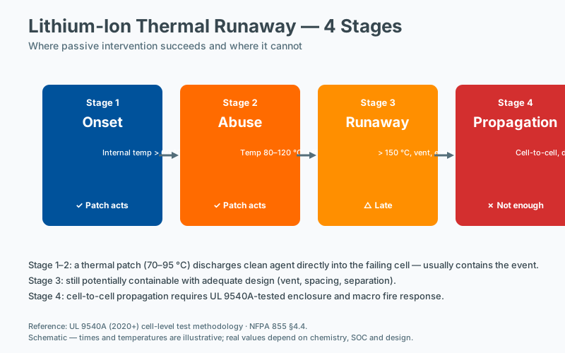
A modern application: lithium-ion battery thermal runaway generates internal cell temperatures of 600–900 °C, releasing flammable electrolyte vapors (flash point ~30 °C for typical carbonate solvents). The interaction between AIT (often > 400 °C for these solvents) and externally heated surfaces from the runaway cell is the reason BESS containers are designed with deflagration venting and dedicated gas detection.
6. Comparative Table: Common Industrial Fluids
The following table compiles representative values drawn from peer-reviewed sources and standard reference data. All values are typical and may vary with grade, additives, and source.
FluidFlash Point (closed cup)Fire PointAuto-Ignition Temp (AIT)Vapor Density (air=1)LFL / UFL (% vol)Common Test MethodGasoline (unleaded)−43 °C−21 °C246–280 °C3.0–4.01.4 / 7.6ASTM D56Diesel fuel (No. 2)52–96 °C (typical 60 °C)65–85 °C210–260 °C~5.00.6 / 7.5ASTM D93 Proc. BKerosene (Jet A)38–72 °C49–85 °C210 °C~4.50.6 / 4.9ASTM D93Fuel oil No. 6 (Bunker)60–110 °C75–120 °C245–330 °C> 51.0 / 5.0ASTM D93Transformer oil (mineral)140–160 °C160–180 °C300–350 °C> 50.6 / 6.5ASTM D92 (open)Hydraulic fluid (mineral, ISO VG 46)180–210 °C200–230 °C330–360 °C> 50.5 / 5.0ASTM D92Hydraulic fluid (phosphate ester)235–280 °C270–310 °C540–600 °C> 6~0.7 / 7.0ASTM D92Ethanol (anhydrous)13 °C18 °C363 °C1.63.3 / 19.0ASTM D56Methanol11 °C16 °C464 °C1.16.0 / 36.5ASTM D56Acetone−20 °C−9 °C465 °C2.02.6 / 12.8ASTM D56Toluene4 °C16 °C480 °C3.11.2 / 7.1ASTM D56Heptane (n)−4 °C7 °C204 °C3.51.0 / 6.7ASTM D56Diethyl ether−45 °C−21 °C160 °C2.61.9 / 36.0ASTM D56Methyl ethyl ketone (MEK)−9 °C1 °C404 °C2.51.8 / 10
Frequently Asked Questions
How do oxygen concentration and fuel type interact in enclosed fires?
Fire requires fuel, oxygen, and an ignition source in proportions that allow sustained combustion. Reducing oxygen concentration below the limiting oxygen concentration (LOC) for the specific fuel extinguishes the fire. Clean-agent systems are designed to reduce oxygen concentration or to interrupt the radical-chain reactions of the flame, depending on the agent.
Can a fire start without an external ignition source?
Yes, through self-heating. Some materials (oils, certain chemicals, lithium cells under abuse) generate heat internally and can reach ignition temperature without an external flame or spark. Self-heating is a recognized fire cause in industrial settings and is one reason passive thermal-activated suppression is specified for unattended enclosures.
What determines whether a fire will self-extinguish?
A fire self-extinguishes when the heat losses to the surroundings exceed the heat generated by the combustion. This balance depends on fuel properties, ventilation, and enclosure geometry. In a well-ventilated enclosure with limited fuel, a small fire may self-extinguish; in a confined enclosure with an abundant fire load, the same fire will grow. This is why enclosure sealing and fuel loading are central to suppression design.
What is the relationship between ventilation and fire growth rate?
Ventilation controls the rate at which oxygen is supplied to the fire, which in turn controls the heat-release rate. In a fuel-controlled fire, additional ventilation increases heat release; in a ventilation-controlled fire, additional ventilation has limited effect. Understanding which regime applies to a given enclosure is essential to sizing both detection and suppression.