Abstract
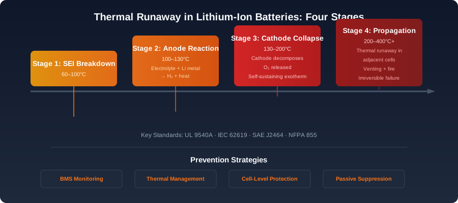
Figure 1: The four stages of thermal runaway in a lithium-ion cell — from initial SEI breakdown to full propagation across adjacent cells. Prevention strategies at each stage are shown below.
Lithium-ion batteries power modern portable electronics, electric vehicles (EVs), and grid-scale energy storage systems (ESS). Their high energy density, however, presents a fundamental safety challenge: thermal runaway (TR). This article provides a comprehensive technical examination of thermal runaway, from the electrochemical origins within a single cell to propagation across modules and packs. We detail the four-stage progression of TR, analyze the composition of vented gases, survey the principal international safety standards governing TR testing, and review prevention strategies spanning cell chemistry, pack architecture, battery management systems, and active suppression. The article concludes with an analysis of real-world failure data drawn from publicly documented ESS and EV incidents and a forward-looking discussion of regulatory and engineering trends.
1. Introduction
 Stages of lithium-ion thermal runaway
A typical 18650 cylindrical cell stores approximately 9–12 Wh in roughly 17 cm³, an energy density that makes lithium-ion chemistry nearly impossible to displace in mobile applications. The same property, however, means that when internal short circuits, mechanical abuse, overcharge, or external heating exceed the cell’s ability to dissipate heat, stored chemical energy can be released violently. The result is a self-sustaining exothermic reaction chain known as thermal runaway, during which cell temperatures can exceed 1000 °C within seconds and adjacent cells may be ignited by ejected electrolyte and conductive debris.
Understanding the mechanism is the first step in preventing it. Engineers, integrators, and regulators must internalize that thermal runaway is not a single event but a multi-stage cascade, and that mitigation at the cell level, module level, and system level follows distinct design principles.
2. Chemical Mechanism of Thermal Runaway
Thermal runaway arises from a sequence of exothermic reactions that progressively consume the cell’s internal components. The four principal reaction zones are the solid electrolyte interphase (SEI), the anode–electrolyte interface, the cathode, and the electrolyte itself. Each has a characteristic onset temperature, and the cumulative heat release exceeds the cell’s heat dissipation capacity once a critical temperature is crossed.
2.1 SEI Decomposition (~80–120 °C)
The SEI is a passivation layer formed on the graphite anode during initial cycling. Composed mainly of lithium carbonate, lithium alkyl carbonates, and lithium fluoride, it is kinetically stable at normal operating temperatures but metastable in a thermodynamic sense. Once the cell interior exceeds approximately 80–120 °C, the SEI begins to decompose, primarily through reactions such as:
(CH₂OCO₂Li)₂ → Li₂CO₃ + CO₂ + C₂H₄ + ½O₂
The decomposition products expose the lithiated graphite anode to direct contact with the electrolyte, initiating secondary reactions that release additional heat. Because SEI decomposition is the first reaction to be triggered, it is often considered the “trigger event” for thermal runaway in cells that have not been subjected to catastrophic mechanical abuse.
2.2 Anode–Electrolyte Reaction (~100–150 °C)
Exposed lithiated graphite (LiC₆) reacts exothermically with the carbonate solvents commonly used in lithium-ion electrolytes—ethylene carbonate (EC), dimethyl carbonate (DMC), ethyl methyl carbonate (EMC), and propylene carbonate (PC). The reaction:
LiC₆ + EC/DMC/EMC → Li₂CO₃ + hydrocarbons + heat
is the dominant heat source in many TR events. The enthalpy of reaction is roughly 1500–1700 J per gram of lithiated graphite, and the kinetics accelerate rapidly with temperature. Once this reaction begins, heat generation outpaces external cooling in nearly all practical pack configurations.
2.3 Cathode Decomposition (~150–300 °C, chemistry-dependent)
The cathode material—NMC (nickel manganese cobalt), NCA (nickel cobalt aluminum), LFP (lithium iron phosphate), or LMO (lithium manganese oxide)—releases oxygen at elevated temperatures, which then oxidizes the electrolyte. The onset temperature and exotherm magnitude depend strongly on chemistry:
| Cathode | Oxygen release onset | Relative heat release |
|---|---|---|
| NMC811 | ~180 °C | Very high |
| NMC111 | ~220 °C | High |
| NCA | ~190 °C | High |
| LFP | >300 °C (limited O₂ release) | Low |
The reaction of released oxygen with the electrolyte:
Cathode → Metal oxide + ½O₂ O₂ + electrolyte → CO₂ + H₂O + heat
is responsible for the highest peak temperatures and is the dominant reaction in cells that use nickel-rich cathodes.
2.4 Electrolyte Combustion and Internal Short Circuit
Once temperatures exceed ~200 °C, the separator (typically polyethylene or polypropylene, sometimes with a ceramic coating) melts and shrinks, causing internal short circuits between anode and cathode. The ensuing Joule heating, combined with electrolyte vaporization, leads to cell venting. Vented electrolyte vapors can ignite when they encounter the hot cell surface or an external spark, producing jet-like flames and adding combustion heat to the exothermic cascade.
3. Stages of Thermal Runaway
Industry standards and academic literature typically divide TR into four stages. The boundaries between stages are not strictly defined in temperature terms because onset temperatures vary with chemistry, state of charge (SOC), age, and abuse history, but the qualitative progression is consistent.
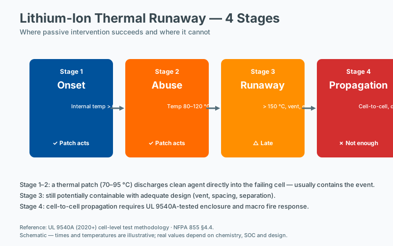
Stage 1: Onset / Self-Heating
Stage 1 is the period in which internal reactions begin but have not yet overwhelmed the cell’s thermal mass. The defining criterion is a sustained temperature rise above ambient without external heating, typically a heating rate greater than 0.1–0.2 °C/min. Cells in Stage 1 may be recoverable if the heat source (overcharge current, external heater, short circuit) is removed quickly enough.
Stage 2: Acceleration
The heating rate increases nonlinearly as SEI decomposition and anode–electrolyte reactions dominate. The cell typically reaches 150–250 °C. Internal pressure rises as volatile decomposition products accumulate, and the cell begins to bulge. This stage can last from tens of seconds to several minutes depending on cooling conditions and SOC.
Stage 3: Venting and Combustion
At ~250–350 °C, the safety vent (a scored aluminum disc or similar pressure-relief feature) opens, releasing a high-velocity jet of flammable gas and electrolyte vapor. The vent gas often ignites immediately, producing a sustained flame at the vent orifice. Temperatures in the jet can exceed 1000 °C. In modules with multiple cells, this jet flame is the primary propagation vector to neighboring cells.
Stage 4: Propagation / Full Thermal Runaway
If adjacent cells absorb sufficient heat (typically through radiation, conduction through the module housing, or direct flame contact), they enter Stage 2 and the cascade spreads. In a tightly packed module, propagation from one cell to the next can occur within 30–120 seconds. Once propagation begins, only active suppression or massive thermal isolation can halt it. Failure to contain Stage 4 propagation is the defining characteristic of a major battery fire incident.
4. Vent Gas Composition
The vent gas is a complex mixture of hydrocarbons, hydrogen, carbon oxides, and various volatile organic compounds (VOCs). Composition varies with cell chemistry, SOC, and stage of TR, but typical analyses from published studies and incident reports show the following approximate ranges on a volume basis:
| Component | Typical range (vol %) | Hazard |
|---|---|---|
| H₂ | 20–40 | Flammable, explosive |
| CO | 10–30 | Toxic, flammable |
| CO₂ | 10–30 | Asphyxiant, indicates combustion |
| CH₄ | 5–15 | Flammable |
| C₂H₄ / C₃H₆ | 5–15 | Flammable, reactive |
| Electrolyte vapors (DMC, EMC, EC) | 2–10 | Flammable, toxic |
| HF (hydrogen fluoride) | <1% but highly toxic | Corrosive, inhalation hazard |
The high hydrogen fraction is one of the most dangerous features of vented lithium-ion cells. H₂ has a lower flammability limit of 4 vol % in air and a detonation range of 18–59 vol %. Even after a fire is suppressed, hydrogen can accumulate in enclosed spaces (parking garages, battery rooms, BESS containers) and ignite later from a hot surface or spark, causing secondary explosions. This hazard is a central focus of UL 9540A and NFPA 855.
Hydrogen fluoride is generated by decomposition of the LiPF₆ salt used in most electrolytes. Concentrations in vent gas are typically low (<1000 ppm), but the IDLH (Immediately Dangerous to Life or Health) value for HF is only 30 ppm, so even small leaks in confined spaces can be lethal.
5. Test Standards
A range of international standards governs thermal runaway testing, cell-level abuse tolerance, and system-level fire propagation. The most important are summarized below.
5.1 UL 9540A
UL 9540A, “Test Method for Evaluating Thermal Runaway Fire Propagation,” is the de facto North American standard for BESS installations. It defines a four-tier testing methodology:
- Cell-level test: Initiate TR in a single cell via heating, nail penetration, or overcharge, and measure heat release, vent gas composition, and surface temperature.
- Module-level test: Assemble a representative module, initiate TR in one cell, and determine whether propagation occurs.
- Unit-level test: Test the full BESS unit in its enclosure, measuring external heat flux, gas generation, and whether fire spreads beyond the unit.
- Installation-level test: Field test of the complete installation, addressing gas accumulation, deflagration risk, and fire spread to surrounding equipment.
UL 9540A is referenced by NFPA 855 and by many U.S. jurisdictions in their fire codes. A successful UL 9540A test report is required for permit approval in most large-scale ESS installations in the United States.
5.2 IEC 62619
IEC 62619 is the international standard for secondary lithium cells and batteries used in industrial applications, including stationary ESS. It specifies abuse tests including external short circuit, impact, drop, thermal abuse, overcharge, and forced discharge. While it does not address system-level propagation in the same depth as UL 9540A, it is widely accepted for certification of cells and modules for industrial use.
5.3 SAE J2464
SAE J2464, “Electric and Hybrid Electric Vehicle Rechargeable Energy Storage System (RESS) Safety and Abuse Testing,” is the principal standard for EV battery abuse testing in North America. It defines single-cell and full-pack tests including:
- Mechanical: penetration, crush, drop, immersion, vibration
- Thermal: external heating, thermal cycling, thermal shock
- Electrical: overcharge, overdischarge, external short, ripple
J2464 is widely cited in EV battery safety literature, though it is gradually being supplemented by GB/T 36276 (China), ISO 6469-1 and -4 (general road vehicles), and the newer UN 38.3 Rev. 7 transport tests.
5.4 Other Relevant Standards
- UN 38.3: Transport testing (altitude simulation, thermal cycling, vibration, shock, external short, impact, overcharge, forced discharge). Mandatory for shipping lithium-ion cells by air or sea.
- UL 1973: Cells and modules for stationary and motive applications in North America.
- GB/T 36276: Chinese standard for lithium-ion cells and modules used in ESS, with detailed TR and propagation requirements.
- ISO 26262: Functional safety standard for automotive electrical systems; covers BMS software safety requirements.
- NFPA 855: U.S. installation standard for stationary energy storage, including spacing, fire suppression, and gas detection requirements.
6. Prevention Strategies
Prevention is necessarily layered. No single intervention is sufficient; the practical approach combines chemistry-level improvements, cell-level mechanical protection, module-level architecture, and system-level controls.
6.1 Battery Management System (BMS)
The BMS is the first line of defense. Its functions relevant to thermal runaway include:
- Voltage monitoring: per-cell voltage with typically ±5 mV accuracy to detect overcharge (>4.2 V for most Li-ion chemistries) and overdischarge (<2.5 V).
- Current monitoring: detect short circuits (via dI/dt thresholds) and excessive charge/discharge currents.
- Temperature monitoring: multiple thermistors per module, often five to ten, with rates of rise (dT/dt) detection to flag incipient self-heating.
- State-of-charge (SOC) and state-of-health (SOH) estimation: avoid operating at very high SOC (>90%) in hot environments and detect early degradation that may increase TR risk.
- Fault response: disconnect contactors, activate cooling, throttle charge rate, communicate faults to vehicle or system controller.
- Functional safety compliance: ISO 26262 ASIL C or D for EVs; IEC 61508 SIL 2 or 3 for ESS.
Modern BMS architectures use dual-redundant voltage and temperature acquisition and incorporate diagnostics that can detect a single faulty sensor without taking the system offline.
6.2 Thermal Management
Thermal management systems are classified as passive, active, or hybrid.
Passive systems include phase change materials (PCMs), heat-absorbing fillers, and insulating barriers between cells. PCMs such as paraffin or hydrated salts absorb heat during the latent phase transition and delay propagation by tens of seconds to several minutes, which is often enough for a BMS to react and isolate the affected module.
Active systems include:
- Air cooling: low cost, low density, suitable for small consumer packs and some stationary modules.
- Liquid cooling (water-glycol or dielectric fluids): dominant in modern EVs and grid ESS, offering heat transfer coefficients of 1000–5000 W/m²·K, roughly an order of magnitude better than air.
- Refrigerant cooling: used in some high-performance EVs and aerospace applications for direct two-phase cooling of modules.
Hybrid systems combine active cooling with PCM to handle peak transient loads.
6.3 Passive Suppression
Passive suppression technologies function without external power or control signals:
- Thermal barriers: aerogel, mica, or intumescent sheets between cells that swell when heated and provide thermal insulation.
- Cell-level fuses: positive temperature coefficient (PTC) elements in the cell tab that increase resistance sharply when overheated, limiting fault current.
- Current interrupt devices (CID): mechanical pressure switches that disconnect the cell internally if internal pressure exceeds a threshold.
- Shutdown separators: polymer separators (e.g., polyethylene with ceramic coating) that lose porosity above ~130 °C, blocking ionic conduction and effectively shutting the cell down.
6.4 Active Suppression and Containment
Active suppression is required in large ESS installations and increasingly in EV packs:
- Clean agent suppression: Novec 1230 or FM-200 systems that extinguish fires without damaging electronics.
- Water mist / water spray: highly effective for lithium-ion fires despite historical preference for dry agents; water cools adjacent cells and reduces propagation probability.
- Ventilation and gas detection: hydrogen sensors with automatic exhaust activation to prevent gas accumulation to the lower flammability limit.
- Deflagration panels: explosion-relief vents in BESS containers that prevent overpressure damage to the enclosure during rapid gas combustion.
- Module isolation: thermally fused barriers that expand to isolate a faulted module from adjacent ones.
7. Real-World Failure Data
Public incident data from ESS and EV operators provides valuable empirical validation of lab-scale TR research.
7.1 Energy Storage System Incidents
- McMicken BESS, Surprise, AZ, April 2019: A 2.16 MWh BESS installed by Arizona Public Service experienced a cascading TR event involving 26 battery racks over several hours. The root cause was determined to be an internal cell defect combined with inadequate gas detection and ventilation. The event drove significant revisions to UL 9540A and NFPA 855, particularly regarding gas accumulation thresholds.
- Moss Landing BESS, Monterey County, CA, January 2025: One of the largest BESS facilities in the world (~400 MWh) suffered a major fire and subsequent re-ignition. While the full root cause investigation is ongoing as of the time of writing, preliminary findings cited thermal runaway in rack-mounted modules and difficulties in achieving suppression due to hydrogen generation and re-ignition from stranded energy.
- Largo ESS Fire, MD, 2024: A smaller commercial BESS installation experienced a TR event that was successfully contained to a single module, attributed in part to fluid-cooled architecture and rapid isolation by the BMS.
7.2 Electric Vehicle Incidents
- Chevrolet Bolt EV Recall, 2020–2021: LG Energy Solution cells manufactured at two Korean facilities exhibited manufacturing defects (folded anode tab and separator misalignment) that led to multiple fires. The recall covered more than 140,000 vehicles and cost approximately $2 billion.
- Tesla Model S and Model 3 Fires, 2013–2023: Following high-profile collisions and battery fires, Tesla revised its pack architecture to include more substantial module-to-module barriers and improved active cooling. Most post-2018 Tesla fires involve single-module events that do not propagate to the full pack.
- Hyundai Kona EV Recall, 2020–2021: A high-voltage battery manufacturing defect led to 15 reported fires in Korea, Canada, and Europe. The recall affected more than 80,000 vehicles.
- NIO ES8 Battery Swap Station Fire, 2022: An NIO swap station in Henan, China, experienced a fire during battery handling. No injuries were reported, and the investigation cited a cell defect combined with inadequate pre-storage thermal checks.
A common thread across these incidents is that the root cause is rarely a single failure mode; it is typically a combination of a cell-level defect (manufacturing variability, contamination, separator damage) and a system-level weakness (insufficient propagation resistance, gas accumulation, suppression failure). This reinforces the need for defense-in-depth design.
8. Regulatory and Engineering Trends
Several developments are reshaping the field in 2025–2026:
- LFP chemistry adoption: LFP’s much higher thermal stability (>300 °C onset vs. ~180 °C for NMC811) has driven its adoption in standard-range EVs and grid ESS, with the trade-off of lower energy density.
- Sodium-ion emergence: Sodium-ion chemistries under commercialization (CATL, BYD, Northvolt) avoid lithium altogether and offer TR profiles competitive with LFP, though cycle life and energy density remain limitations.
- Solid-state batteries: Toyota, Samsung SDI, QuantumScape, and others are pursuing sulfide- and oxide-based solid electrolytes that promise non-flammable separators, though manufacturing scale and dendrite suppression remain unsolved at the time of writing.
- **Stranded energy standards
Frequently Asked Questions
How does passive suppression differ from BMS-based protection?
A BMS detects electrical anomalies and disconnects at the cell or string level, but it relies on sensors, wiring, and control logic that can fail during the very event it is meant to manage. Passive suppression operates without external power or signal input: a thermally activated device releases its agent directly into the enclosure once a design threshold is reached. The two layers are complementary; the BMS limits fault propagation upstream, passive suppression contains the downstream thermal event.
Does passive suppression work for LFP as well as NMC batteries?
Both LFP (lithium iron phosphate) and NMC (nickel manganese cobalt) chemistries can undergo thermal runaway, though LFP typically releases less energy per cell and may not propagate as readily as NMC. Standards such as UL 1973 and IEC 62619 treat both chemistries as requiring propagation prevention, and UL 9540A is applied at the cabinet level regardless of chemistry. Suppression device selection should be based on the tested propagation behavior of the specific cabinet configuration rather than chemistry alone.
Can a fire in one battery cell spread to adjacent cells?
Yes. Once a cell enters thermal runaway, vented gas and radiant heat can propagate failure to neighboring cells within seconds to minutes, depending on cell spacing, state of charge, and module geometry. UL 9540A testing characterizes this propagation behavior at the cabinet level, and NFPA 855 treats propagation prevention as a primary design objective for stationary energy storage. Physical separation, thermal barriers, and suppression devices are commonly combined to interrupt the propagation chain.
What gas sensors detect early battery failure?
Early battery failure is typically detected through off-gas sensors that respond to the electrolyte vapor vented during the early stages of thermal runaway, well before cell temperature rises measurably. Commonly monitored species include hydrogen, carbon monoxide, and certain volatile organic compounds specific to the cell chemistry. Sensor placement inside the enclosure and a response threshold well below thermal-runaway temperature are required for the warning to be acted upon before propagation occurs.