Guides # Choosing Activation Temperature Passive Fire Patch Editorial Team 2026-08-07 ## yaml title: “Choosing the Right Activation Temperature for Fire Patches” date: 2026-08-07 slug: choosing-the-right-activation-temperature-for-fire-patches description: “Comprehensive engineering guide to selecting the optimal activation temperature for passive fire suppression patches, covering thermal dynamics, equipment profiles, environmental factors, and standards.”
Fire suppression patches — thin, adhesive, thermally triggered composite devices that discharge an extinguishing agent directly onto a fire source — rely on a single, irreversible decision point: the temperature at which their reactive layer activates. Select that threshold correctly and the patch delivers a fast, targeted response that contains a fault before it propagates. Select it poorly and either the patch never fires when it should, or it discharges during benign thermal events, wasting the unit and potentially damaging sensitive equipment.
This guide provides a structured engineering approach to choosing the correct activation temperature for fire patches used inside electrical enclosures, control cabinets, battery housings, and similar confined spaces. It expands on the basic selection table found in most product datasheets and addresses the thermal, environmental, and fire-growth factors that determine whether a 140°C, 170°C, or 200°C patch is the appropriate choice for a given application.
How Fire Patch Activation Works
 Thermal activation thresholds by stage
A fire patch contains one or more layers of a thermally reactive composite bonded to a carrier film. The composite typically comprises a binder, an oxidizer, and an extinguishing agent precursor — frequently a solid propellant or intumescent material that, when heated above a defined threshold, decomposes exothermically and discharges the agent as a gas, aerosol, or fine particulate cloud directly into the enclosure.
The activation point is controlled by the binder chemistry and the laminate construction. Common binder systems include:
- Thermoplastic adhesives that soften and release the agent at a defined softening point (typically 140–160°C).
- Thermally curing resins that depolymerise above a glass transition temperature (often 170–190°C).
- Inorganic binders such as silicone-modified ceramics or phosphate systems, engineered for higher activation thresholds (190–220°C) and improved long-term aging stability.
Each system has its own thermal kinetics, aging behaviour, and tolerance to humidity. The activation temperature published on a datasheet is the temperature at which the patch reliably triggers in still air under laboratory conditions, typically per a method derived from UL 9540A (Test Method for Evaluating Thermal Runaway Fire Propagation), EN 54-1 principles, or the manufacturer’s internal protocol.
Standard Activation Temperatures and Color Coding
Although manufacturers vary, a de facto industry convention has emerged for the three most common activation thresholds. Color-coded labels and packaging simplify field identification, but always confirm the value printed on the device itself before installation.
| Nominal Activation | Color Code | Typical Application |
|---|---|---|
| 140°C (284°F) | Blue | Sensitive electronics with low thermal tolerance; sealed enclosures with tight clearances |
| 170°C (338°F) | Orange (industry standard) | General electrical equipment, server racks, control panels, low-voltage distribution |
| 200°C (392°F) | Red | High-temperature equipment, industrial enclosures, photovoltaic inverters, machinery cabinets |
Some manufacturers offer activation temperatures at finer increments — typically every 5°C between 140°C and 200°C — and can produce custom thresholds for OEM orders. Custom values outside this band (below 120°C or above 220°C) are possible but require careful validation of aging behaviour and shelf life.
Selection Factor 1: Normal Operating Temperature
The single most important factor is the steady-state and peak temperature inside the enclosure where the patch will be installed. The activation temperature must be at least 30–50°C above the maximum normal operating temperature at the patch location — not at the enclosure exterior, and not at the equipment’s nameplate rating.
This 30–50°C margin accounts for:
- Transient overshoot during startup or peak load
- Localised hot spots near heatsinks, busbars, transformers, or rectifier stacks
- Solar gain through enclosure walls (potentially 20–30°C above ambient on dark, unventilated cabinets)
- The thermal gradient between the device being protected and the patch mounting surface
The table below summarises typical maximum internal ambient temperatures and recommended patch activation thresholds for common enclosure types.
| Enclosure Type | Typical Max Internal Ambient | Recommended Activation |
|---|---|---|
| Office server room rack | 35–40°C | 140°C or 170°C |
| Edge data centre (uncontrolled HVAC) | 45–55°C | 170°C |
| Outdoor telecom cabinet (direct sun) | 60–70°C | 200°C |
| Industrial control panel (factory floor) | 50–65°C | 170°C or 200°C |
| Solar inverter enclosure | 65–80°C | 200°C |
| Li-ion battery cabinet (passive cooling) | 35–45°C | 170°C |
| EV charging station | 55–70°C | 170°C or 200°C |
| Welding equipment cabinet | 60–75°C | 200°C |
When measuring actual operating temperature, use a calibrated thermocouple or data logger placed at the proposed patch location, not at the equipment’s surface. Allow the system to run through a full duty cycle — including worst-case ambient conditions — and record the highest sustained temperature. A margin of 30°C is acceptable for benign indoor environments; 50°C is prudent for outdoor, industrial, or thermally dynamic installations.
Selection Factor 2: Fire Growth Rate
The activation temperature determines how much damage occurs before the patch fires. This must be balanced against the speed at which a fault can become a fully developed fire in the specific enclosure.
Fast-growing fire scenarios include:
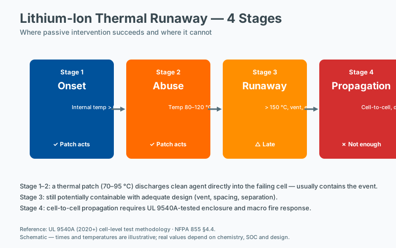
- Lithium-ion battery thermal runaway. Once a cell vents, the adjacent cells can follow within seconds to minutes. UL 9540A testing has shown propagation times as short as 30–90 seconds in densely packed modules. A lower activation temperature (140–170°C) is appropriate because the goal is to interrupt the runaway before cascading propagation occurs.
- Insulating oil or solvent fires in transformer or rectifier enclosures.
- Enclosures containing flammable gases or vapours from leaks upstream.
Slow-growing fire scenarios include:
- Overheated wiring in conventional LV distribution
- Smouldering faults in control electronics
- Arcing events in well-ventilated cabinets
In these cases, a 170°C or 200°C patch is usually sufficient because the fault will generate enough heat to cross the threshold before significant damage occurs, while the higher activation temperature greatly reduces the risk of nuisance discharge.
For mixed-risk enclosures — for example, a control cabinet that also houses a small Li-ion backup module — a 170°C patch typically offers the best compromise.
Selection Factor 3: Ambient Climate
The geographic and microclimatic environment of the installation has a direct effect on both the patch’s effective activation margin and the risk of nuisance discharge.
- Hot climates (Middle East, Southeast Asia, northern Australia, southern US): internal enclosure temperatures routinely reach 60–75°C. Lean toward higher activation thresholds (200°C) or ensure the 50°C margin is genuinely maintained.
- Cold climates (Northern Europe, Canada, northern US): the low ambient provides a wide thermal headroom. Lower activation temperatures (140–170°C) are safe and provide faster response.
- High-altitude installations above 2,000 m: reduced air density slightly lowers convective heat transfer at the patch surface, which can marginally raise the effective activation temperature. The effect is small (typically 1–3°C), but for installations near the upper edge of a threshold band, confirm with the manufacturer.
- Coastal or humid environments: confirm the patch’s rated humidity range. Some binder systems absorb moisture over time, which can shift activation behaviour by several degrees and reduce shelf life.
- Vibration and mechanical shock environments (rail, heavy industry, mobile equipment): confirm the patch is rated for the relevant vibration profile per IEC 60068-2-6 or equivalent. Mechanical degradation can prematurely expose the reactive layer.
Selection Factor 4: False Activation Risk
False activations are uncommon with correctly specified patches, but the consequences — wasted unit, possible contamination of sensitive equipment, and loss of fire protection until replacement — are not trivial. The principal causes of nuisance discharge are:
- Direct sunlight on outdoor enclosures. Internal temperatures can rise 20–30°C above ambient on dark-coloured, unventilated cabinets during peak insolation. A 170°C patch in such an enclosure may be uncomfortably close to the trigger threshold on a summer afternoon in Dubai or Phoenix.
- Adjacent heat-generating equipment. Transformers, heaters, resistors, and even tightly bundled power cables can create hot spots exceeding the enclosure’s average internal temperature by 15–25°C.
- Poor ventilation. Enclosures with blocked filters or failed fans can trap heat during peak load, particularly in UPS or battery backup cabinets.
- Welding or hot work nearby. Patches mounted close to the exterior wall of a cabinet in an industrial workshop can be exposed to radiant heat during welding operations.
When any of these conditions apply, default to the next higher activation band or implement physical separation (a heat shield, deeper mounting position inside the enclosure, or a baffle) to keep the patch surface temperature within design limits.
Selection Factor 5: Response Time and Detection Latency
The activation temperature also determines how long it takes for the patch to detect a fire. A 140°C patch in a 30°C enclosure will fire roughly 40–60 seconds after a localised fault reaches 140°C, depending on the fire’s energy release rate and the patch’s thermal mass. A 200°C patch in the same enclosure will fire later — typically 20–40 seconds after the local temperature crosses 200°C — but by that point the fault has had more time to grow.
For most applications this trade-off is acceptable. For very fast fire scenarios — particularly Li-ion battery propagation — the additional 20–40 seconds of detection latency at 200°C can be material. Pairing the patch with a complementary detection method (smoke, gas, or rate-of-rise sensor) can compensate, but the simplest approach in fast-growth applications is to choose the lowest activation temperature that still meets the false-activation margin.
Standards and Compliance References
While no single international standard governs fire patch activation temperatures specifically, several frameworks are relevant when specifying and documenting a selection:
- NFPA 75 (Standard for the Fire Protection of Information Technology Equipment) — addresses fire suppression within IT enclosures.
- NFPA 76 (Standard for the Fire Protection of Telecommunications Equipment) — applies to telecom cabinets and data centre telecom rooms.
- NFPA 855 (Standard for the Installation of Stationary Energy Storage Systems) — guidance for battery enclosures, including Li-ion.
- EN 54-1 and the broader EN 54 series — fire detection and fire alarm system components; relevant where the patch forms part of an integrated detection/suppression chain.
- UL 9540A — test method for evaluating thermal runaway fire propagation in battery energy storage systems.
- IEC 62619 — secondary lithium batteries for industrial applications.
- ISO 7240 series — fire detection and alarm systems for buildings.
When documenting the selection for an insurance, audit, or AHJ review, record the basis of the 30–50°C margin (measured temperatures, assumptions, ambient data), the applicable standards considered, and any deviations from the manufacturer’s default recommendation.
The Golden Rule: When in Doubt, Choose 170°C
For the majority of enclosed electrical equipment in temperate, indoor environments, 170°C is the industry default for a reason. It provides a safe margin above normal operating temperatures — typically more than 100°C above the worst-case internal ambient in a 40°C room — while activating early enough to interrupt fire growth before catastrophic damage occurs.
Deviate from 170°C upward (to 200°C) when:
- The enclosure routinely exceeds 60°C internal ambient
- False activation risk from solar gain, adjacent equipment, or poor ventilation is material
- The fire growth rate is slow and additional detection latency is acceptable
Deviate downward (to 140°C) when:
- The enclosure contains fast-propagating fire risks, especially Li-ion cells
- The protected equipment has very low thermal tolerance and cannot survive the heat of a developing fault
- The installation is in a cool, controlled environment with a wide thermal margin
Frequently Asked Questions
What is the first step in assessing fire risk for an enclosure?
The first step is to identify the fire load (what can burn, in what quantity, and with what energy release), followed by the credible ignition sources and the pathways to propagation. Standards such as NFPA 76 and NFPA 855 provide structured assessment methods for specific equipment types. A documented risk assessment is the basis for selecting any suppression technology.
What maintenance records should facility managers keep?
Maintenance records should include the as-installed configuration (device type, location, date of installation), the inspection schedule and results, any replacements or repairs, and the dates of any incident events. NFPA 10 and most insurer guidance require these records to be retained for the life of the installation. Digital records with timestamps simplify audit and incident review.
How does enclosure sealing affect suppression effectiveness?
Enclosure sealing determines how long the suppression agent remains at design concentration. An unsealed enclosure will lose agent through openings faster than the fire can be suppressed; a properly sealed enclosure retains concentration long enough to interrupt the reaction chain. Gasket condition, cable entry sealing, and ventilation management are therefore integral to the suppression design, not separate concerns.
How do I calculate the appropriate suppression capacity?
Suppression capacity is determined by the protected enclosure volume, the fire load, and the specific suppression agent. For gaseous systems, design concentration targets are defined in NFPA 2001 and ISO 14520; for passive point-of-origin devices, the manufacturer's tested performance for the specific enclosure volume and geometry applies. Engineering judgment, supported by manufacturer data and, where relevant, third-party listing, is required.