How Microencapsulated Fire Patches Work: The Science Behind the Technology
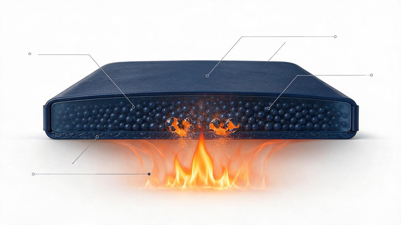
Figure 1: Cross-section of a microencapsulated fire suppression patch. Heat from a fire causes the microcapsules to rupture, releasing the extinguishing agent at the point of ignition.
A passive fire patch looks almost ordinary: a thin, rigid plate roughly the size of a paperback book, laminated with a peel-and-stick adhesive backing, mounted on the interior wall of an electrical enclosure or a small equipment cabinet. There are no pressure gauges, no piping, no moving parts, no electronics. And yet, within seconds of a fire igniting inside that enclosure, the patch releases a precisely metered dose of clean suppression agent that extinguishes the flame before it can spread. The technology that makes this possible is microencapsulation — a discipline borrowed from pharmaceuticals, food science, and specialty chemicals, and adapted for one of the most demanding applications in fire protection.
This article provides an in-depth technical examination of how microencapsulated fire patches work, the materials science behind them, the engineering tolerances required for reliable activation, the standards that govern their design, and where the technology is heading next.
The Core Technology: Microencapsulation
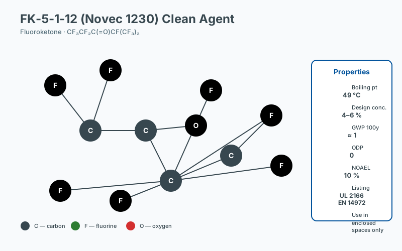 FK-5-1-12 molecule structure
Microencapsulation is the process of enclosing microscopic droplets or particles of an active substance inside a continuous polymeric shell. The resulting microcapsules typically range from 1 micron to 500 microns in diameter, though most fire-suppression patches use capsules in the 50–200 micron range. By comparison, a human hair is approximately 70 microns thick, so the capsules sit at the very edge of unaided visual perception.
The concept dates back to the 1950s when the National Cash Register Company developed carbonless copy paper using microencapsulated dyes. Since then, the technique has matured into a sophisticated branch of engineered materials, with applications spanning pharmaceuticals, agrochemicals, self-healing polymers, fragrances, and — relevant here — clean-agent fire suppression.
In a fire patch, microencapsulation serves three engineering objectives simultaneously:
- Containment of a volatile liquid suppression agent in a stable solid form for years.
- Triggered release at a precisely defined temperature.
- Uniform, simultaneous deployment of all capsules across the patch surface to achieve design concentration rapidly.
The Capsule Structure
Each microcapsule in a fire suppression patch is a composite particle with two functionally distinct regions: a liquid core and a polymeric shell.
The Core: Clean Suppression Agent
The core typically contains a fluoroketone, most commonly FK-5-1-12 (chemical name: dodecafluoro-2-methylpentan-3-one), marketed under the trade name Novec 1230 (3M). It is one of the second-generation clean agents replacing the ozone-depleting hydrochlorofluorocarbons (HCFCs) and hydrofluorocarbons (HFCs) phased out under the Montreal Protocol and subsequent F-Gas Regulation (EU 517/2014).
Key properties that make FK-5-1-12 suitable for microencapsulation include:
- Boiling point of 49°C — well above typical ambient enclosure temperatures, ensuring the liquid stays condensed inside the capsule.
- Low toxicity — acceptable for occupied spaces, with a design concentration well below the No Observed Adverse Effect Level (NOAEL).
- Zero ozone depletion potential (ODP) and a global warming potential (GWP) of less than 1.
- Extinguishing mechanism — primarily physical: it removes heat through endothermic vaporization and disrupts combustion chain reactions at the molecular level.
For the patch designer, the agent’s relatively low boiling point is both a benefit and a constraint: it vaporizes rapidly when released, but it must remain stable inside the capsule for the entire service life of the product — typically 10 years or more.
The Shell: An Engineered Polymer
The shell is the heart of the technology. It must perform contradictory functions simultaneously: remain impermeable to the liquid core for years under thermal cycling, yet fail catastrophically and almost instantaneously at a precisely defined activation temperature.
Common shell chemistries used in fire suppression patches include:
- Melamine-formaldehyde (MF) resins — rigid, high-temperature resistant, well-established in industrial microencapsulation.
- Polyurethane (PU) systems — tunable activation temperatures through polyol selection.
- Acrylic copolymers — used in some lower-activation-temperature formulations.
The shell’s key engineered properties are:
- Thermal stability up to roughly 120°C in continuous service.
- A sharply defined melting or decomposition point, typically tuned to 170°C ± 5°C, which corresponds to the thermal signature of an actively growing enclosure fire.
- Mechanical robustness sufficient to survive shipping, handling, and vibration inside industrial equipment without premature rupture.
- Low permeability to FK-5-1-12 over multi-year timescales, ensuring agent retention meets the design dosage at the moment of activation.
The Polymer Matrix
Microcapsules are not simply glued to a backing in loose powder form. They are embedded within a solid polymer matrix — a continuous phase that performs several engineering functions simultaneously:
- Spatial distribution — the matrix holds thousands or millions of capsules in a uniform three-dimensional distribution across the patch’s surface area and through its thickness.
- Mechanical protection — the matrix absorbs impacts, vibration, and abrasion that might otherwise damage individual capsules during installation or service.
- Thermal conductivity — heat-conductive fillers (often metallic or ceramic powders such as aluminum oxide or boron nitride) are compounded into the matrix to eliminate temperature gradients across the patch. Without this, capsules near the flame would rupture long before those at the patch’s edge, producing a slow, sequential release that fails to reach extinguishing concentration.
- Adhesion — a pressure-sensitive adhesive layer, typically an acrylic or rubber-resin system, provides peel-and-stick mounting to cleaned enclosure surfaces. The adhesive is selected to withstand the same temperature range as the matrix.
- Substrate — the back of the matrix may incorporate a thin foil, fiberglass, or high-temperature polymer carrier to provide dimensional stability.
The result is a laminate, typically 1.5–4 mm thick, that behaves as a single rigid or semi-rigid component.
The Activation Sequence: A Timeline
To understand the engineering challenge, it helps to walk through the activation sequence second by second. The figures below are representative for a typical enclosure fire scenario.
| Time | Temperature | Event |
|---|---|---|
| T = 0 s | 30–50°C (ambient) | Fire ignites — typically a contact failure, overloaded conductor, or lithium-ion cell thermal runaway. Patch is dormant. |
| T = 10–30 s | 100–150°C | Hot plume contacts the patch. Polymer matrix begins conducting heat laterally. Capsules closest to ignition heat fastest, but heat-conductive fillers equalize the thermal field. |
| T = 30–45 s | ~170°C | Polymer shells reach their engineered melting point simultaneously across the patch. This is the critical moment. |
| T = 45–46 s | >170°C | Capsule shells rupture en masse. Liquid FK-5-1-12 is released onto the hot matrix surface and immediately flashes to vapor due to its low boiling point. |
| T = 46–55 s | >170°C, declining | Agent vapor floods the enclosure interior, reaching the design concentration required for extinguishment (typically 4–6% by volume for FK-5-1-12 per NFPA 2001). |
| T = 55–80 s | Cooling | Combustion ceases. Heat is removed endothermically by the vaporizing agent. The enclosure atmosphere stabilizes. |
The total elapsed time from ignition to extinguishment is typically under one minute — often faster than a smoke detector can complete its alarm cycle and signal a building management system.
Why Simultaneous Release Matters
The most subtle and most important engineering challenge in microencapsulated fire patch design is synchronization of rupture. Fire suppression by clean agents requires reaching a minimum design concentration throughout the protected volume. If capsules release sequentially, the agent concentration in the enclosure rises gradually and may plateau below the extinguishing threshold before the patch has fully discharged.
Three design parameters govern synchronization:
- Uniform capsule size distribution — manufacturing tolerances are held to ±5% or tighter on capsule diameter. Because shell thickness scales with diameter, uniform size means uniform shell thickness, which means uniform melt time.
- Uniform dispersion in the matrix — settling, clumping, or surface segregation during manufacture would create regions of high and low capsule density, leading to uneven release. Manufacturers use high-shear mixing and controlled cure cycles to ensure homogeneous distribution.
- Thermal conductivity of the matrix — without conductive fillers, a 5 cm temperature gradient can exist across a small patch during the 30–45 second heat-up phase, causing capsules nearest the flame to rupture seconds before those at the perimeter.
In addition, each production batch is verified to have an activation temperature within ±5°C of the design value. This tolerance is enforced through statistical sampling and differential scanning calorimetry (DSC), as described below.
Testing and Quality Control
Every production batch of microcapsules and finished patches passes through a multi-stage quality regimen before shipment.
Differential Scanning Calorimetry (DSC)
DSC measures the heat flow into a small sample of microcapsules as temperature is ramped at a controlled rate. A sharp endothermic peak at the design activation temperature confirms that the polymer shell is melting within specification. Peak width indicates the uniformity of the shell population.
Accelerated Aging
Samples are stored at elevated temperature (commonly 70–85°C) for periods that simulate long-term ambient exposure. Mass-loss measurements confirm that FK-5-1-12 retention remains within specification after the equivalent of 10 years of service. This is informed by Arrhenius modeling, a standard technique in pharmaceutical shelf-life testing per ICH Q1A guidelines.
Agent Content Verification
Each patch is weighed before and after a destructive test, or sampled non-destructively via gas chromatography, to confirm the correct mass of suppression agent. Typical patch designs carry 30–150 grams of FK-5-1-12 depending on enclosure volume.
Fire Performance Testing
Finished patches are tested in representative enclosure fire scenarios, typically per UL 2166 (the Standard for Halocarbon Clean Agent Extinguishing System Units, applied by analogy) or test protocols derived from NFPA 2001 (Standard on Clean Agent Fire Extinguishing Systems) and ISO 14520 (Gaseous fire-extinguishing systems — Physical properties and system design). Some manufacturers also reference EN 15004 for European market acceptance.
Electrical and Mechanical Safety
Because patches are commonly mounted inside energized electrical cabinets, they must not present a dielectric breakdown hazard, must be non-conductive on the outer surface, and must pass basic mechanical tests such as vibration per IEC 60068-2-6 and thermal cycling per IEC 60068-2-14.
Comparison with Pressurized Cylinder Systems
The most established alternative to microencapsulated patches is the traditional pressurized clean-agent cylinder with a mechanical or electrical actuator. Each approach has distinct strengths.
| Characteristic | Microencapsulated Patch | Pressurized Cylinder |
|---|---|---|
| Agent containment | Solid polymer matrix; no leak path | Pressurized gas (nitrogen) above liquid agent; slow diffusion leak possible |
| Activation mechanism | Thermal (passive) | Electrical signal to solenoid + mechanical valve |
| External power required | No | Yes (detection + control circuit) |
| Failure modes | Few (capsule integrity, adhesive bond) | Valve failure, leak, electrical fault, detector failure |
| Service life | 10 years typical | 5–10 years; hydrostatic retest required at intervals per NFPA 2001 |
| Maintenance | Visual inspection only | Annual visual + 5- or 12-year hydrostatic test |
| Installation footprint | Negligible (mounted inside enclosure) | Significant (external cylinder + piping) |
| Best suited for | Small enclosed volumes — server racks, EV charging enclosures, control cabinets, battery storage modules | Large rooms, data centers, archives, machinery spaces |
The two technologies are not mutually exclusive. Many hybrid systems use cylinder-based suppression for the protected room volume and patches for localized risk inside individual enclosures.
Standards and Regulatory Context
Although no single global standard governs microencapsulated fire patches specifically, the technology draws on several frameworks:
- NFPA 2001 — Standard on Clean Agent Fire Extinguishing Systems. Provides the extinguishing concentration data for FK-5-1-12.
- NFPA 12A — Standard on Carbon Dioxide Extinguishing Systems (referenced for total flooding concepts).
- ISO 14520 — International equivalent of NFPA 2001 for gaseous systems.
- EN 15004 — European standard for fixed gaseous fire-extinguishing systems.
- UL 2166 / UL 2127 — Underwriters Laboratories standards covering clean agent and foam extinguishing units.
- FM Global Approval Standard 5580 — Approval standard for clean agent extinguishing systems.
- IEC 62610 — Mechanical and electrical mounting considerations for equipment inside enclosures.
- EU Regulation 517/2014 (F-Gas Regulation) — restricts high-GWP agents, indirectly favoring FK-5-1-12.
- ASTM E84 / UL 723 — Surface burning characteristics, sometimes invoked for the patch matrix materials.
Compliance with these is typically demonstrated by the patch manufacturer through third-party certification by notified bodies such as UL, FM Global, TÜV, or BRE Global.
Where the Technology Is Heading
Current research and development in microencapsulated fire suppression is moving in several directions:
- Lower activation temperatures — formulations targeting 120–140°C are being developed for use near sensitive electronics where component damage occurs well before 170°C.
- Multi-agent capsules — combining FK-5-1-12 with dry chemical agents or with specialized lithium-ion cell-cooling compounds for battery enclosures.
- Bio-based and biodegradable polymer shells — reducing the environmental footprint of the patch at end of life.
- Smart indicators — passive thermochromic or color-change layers that visibly indicate when a patch has been exposed to near-activation temperatures, even if it did not fully discharge.
- Wireless monitoring integration — though patches remain fundamentally passive, some manufacturers are exploring RFID or NFC tags laminated into the patch for asset tracking and inspection logging without adding electrical connections.
- Higher capsule loading — increasing the suppressant mass per unit area to support larger enclosures, including utility-scale battery energy storage system (BESS) cabinets.
Frequently Asked Questions
What maintenance records should facility managers keep?
Maintenance records should include the as-installed configuration (device type, location, date of installation), the inspection schedule and results, any replacements or repairs, and the dates of any incident events. NFPA 10 and most insurer guidance require these records to be retained for the life of the installation. Digital records with timestamps simplify audit and incident review.
How does enclosure sealing affect suppression effectiveness?
Enclosure sealing determines how long the suppression agent remains at design concentration. An unsealed enclosure will lose agent through openings faster than the fire can be suppressed; a properly sealed enclosure retains concentration long enough to interrupt the reaction chain. Gasket condition, cable entry sealing, and ventilation management are therefore integral to the suppression design, not separate concerns.
How do I calculate the appropriate suppression capacity?
Suppression capacity is determined by the protected enclosure volume, the fire load, and the specific suppression agent. For gaseous systems, design concentration targets are defined in NFPA 2001 and ISO 14520; for passive point-of-origin devices, the manufacturer's tested performance for the specific enclosure volume and geometry applies. Engineering judgment, supported by manufacturer data and, where relevant, third-party listing, is required.
Is third-party certification required for passive suppression devices?
Third-party certification is not always required by code, but it is strongly preferred and often effectively required by AHJs and insurers. A listing from a recognized certification body (UL, FM, VdS, and similar) demonstrates that the device has been tested to a published standard and that production is audited. Unlisted devices should be evaluated carefully and supported by independent test data.