Guides # Electrical Fire Causes Passive Fire Patch Editorial Team 2026-08-07 ## yaml title: “Electrical Fire Causes in Enclosed Equipment: What Actually Starts Fires” date: 2026-08-07
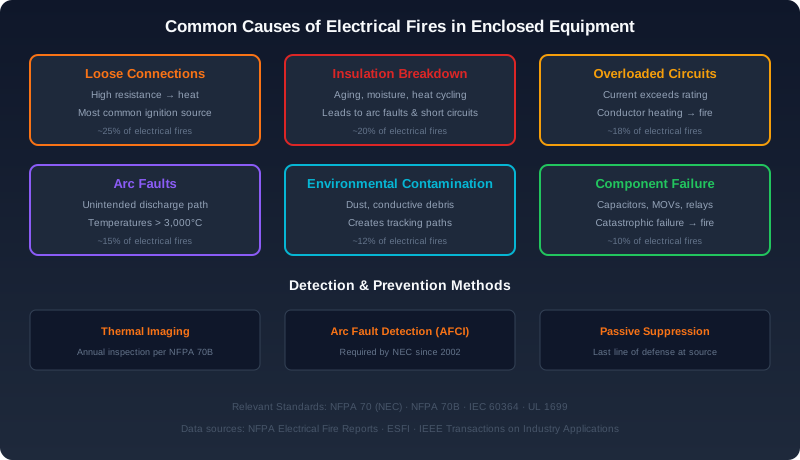
Figure 1: Six common causes of electrical fires in enclosed equipment, ranked by frequency of occurrence with corresponding detection and prevention strategies.
Electrical Fire Causes in Enclosed Equipment: What Actually Starts Fires
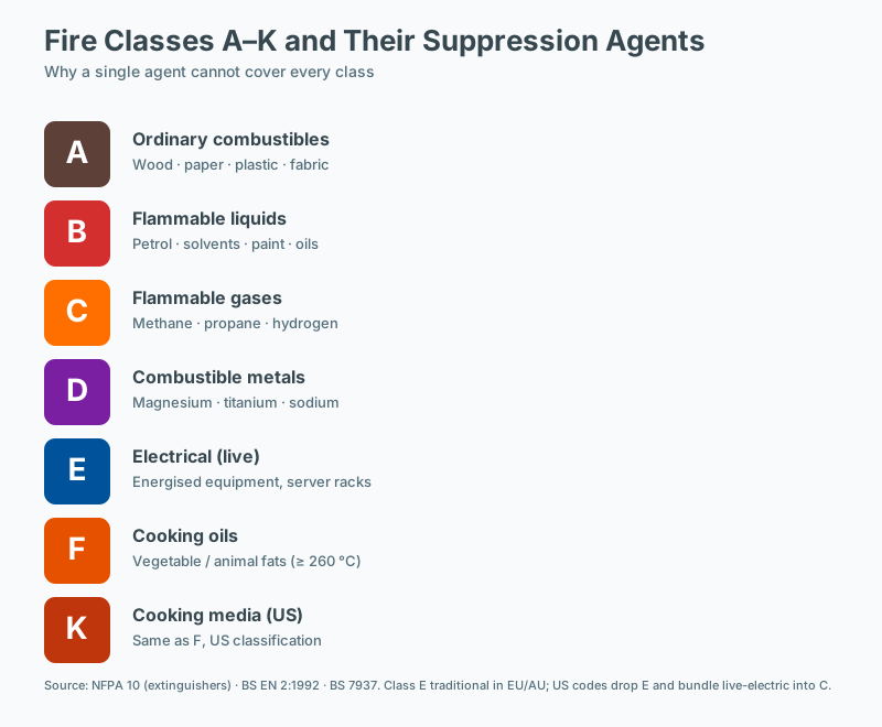 Fire classes A-K and matching suppression agents
Electrical fires inside cabinets, enclosures, and equipment housings account for a disproportionate share of industrial and commercial fire loss. While the global picture of fire ignition is dominated by cooking, heating, and open-flame sources, the fires that cause the largest equipment loss, business interruption, and clean-room contamination are overwhelmingly electrical — and overwhelmingly concentrated inside enclosed equipment where detection is late and suppression is difficult.
This guide consolidates what is known about how these fires start. The data and patterns below draw from insurance loss reports, forensic fire-investigation findings published by agencies such as the U.S. Fire Administration (USFA), the National Fire Protection Association (NFPA), the Fire Investigators Association, and European bodies including the Federation of the European Union Fire Officer Associations (FEU), as well as recurring field patterns reported by maintenance engineers and fire protection designers.
Understanding the ignition mechanism — not just the fuel — is what allows facility teams, designers, and insurers to prioritize interventions that actually reduce risk.
The Top Five Causes, Ranked by Frequency
Frequency rankings vary modestly between geographies and industries, but the ordering below is consistent across most published loss datasets covering low-voltage enclosed equipment (≤ 1000 V AC / 1500 V DC).
1. Loose Electrical Connections — Approximately 35% of Incidents
Loose terminations are the single largest cause of electrical ignition in enclosed equipment. The mechanism is thermal: a high-resistance joint dissipates I²R losses as heat, which in turn oxidizes the contact surface, which raises the resistance further. This positive feedback loop continues until the conductor insulation, terminal block, or surrounding polymeric enclosure reaches its auto-ignition temperature (typically 300–450 °C for common engineering plastics such as PA66, ABS, and PC/ABS blends).
Contributing factors include:
- Thermal cycling. Every load cycle produces expansion and contraction. Aluminum conductors expand roughly 50% more per °C than copper or steel hardware, so aluminum busbar joints are particularly vulnerable unless explicitly designed for creep and oxidation (e.g., Belleville washers, joint compounds compliant with ASTM B912).
- Vibration. Switchgear, transport, rotating machinery, and any equipment near rotating equipment experience constant low-level vibration that backs threaded terminations loose over time. NFPA 70B recommends periodic thermographic inspection specifically to catch this failure mode.
- Improper torque. A frequent root cause flagged in forensic reports is terminations that were never re-torqued after installation, or were torqued with the wrong tool. IEC 61439-1 and UL 845 both require documented torque values for field connections.
- Dissimilar metals. Copper-to-aluminum joints require bimetal lugs and antioxidant compound; bare copper-to-aluminum contact will fail.
Components most affected: busbar joints, breaker line/load terminals, contactor and relay terminations, battery interconnects, and crimped lugs that were not properly crimped with a calibrated tool.
2. Component Failure — Approximately 25%
Modern electronics concentrate enormous energy density into small packages. When an active or passive component fails, it typically fails as a short circuit, drawing current far above the design envelope until a protective device operates — or fails to operate.
- Electrolytic capacitors dry out over time. Their equivalent series resistance (ESR) rises, internal heating increases, and the pressure relief vents open, expelling flammable electrolyte. This is the dominant failure mode in switch-mode power supplies (SMPS), uninterruptible power supplies (UPS), and variable-frequency drives (VFDs). The lifetime rule of thumb is that capacitor life halves for every 10 °C rise above rated temperature (Arrhenius behavior), so a capacitor rated for 10,000 hours at 105 °C may last only a few thousand hours in a hot cabinet.
- Semiconductors — IGBTs, MOSFETs, and rectifier diodes — fail short from thermal overstress, secondary breakdown, or cosmic-ray-induced gate rupture in high-voltage DC systems. VFDs in particular concentrate IGBT failures in the input rectifier and output stage.
- Relays and contactors wear through their contact material. As contact resistance rises, heating accelerates, eventually leading to welding or to a resistive joint that runs hot.
- Batteries — lithium-ion cells can fail through internal short circuits caused by separator damage, dendrite growth, or mechanical abuse. Once a cell goes into thermal runaway, adjacent cells follow, releasing flammable electrolyte vapors.
Standards context: IEC 61508 (functional safety), UL 810A (capacitor safety), and IEC 62619 (secondary lithium cells) all attempt to address component-level reliability through design and qualification rather than inspection.
3. Insulation Breakdown — Approximately 15%
Cable and winding insulation degrades by four overlapping mechanisms:
- Thermal aging. Every insulating material has a thermal endurance curve (e.g., Class B at 130 °C, Class F at 155 °C, Class H at 180 °C). Exceeding the rating accelerates aging exponentially.
- Mechanical fatigue. Vibration, flexing, and bending crack insulation, especially at stress points where cables exit connectors or pass through grommets.
- Chemical attack. Plasticizers and oils attack PVC; certain cleaning agents attack epoxy; ozone (produced by partial discharge) attacks natural rubber.
- Partial discharge. In medium-voltage equipment and high-density power electronics, sub-visible discharges erode insulation progressively until complete breakdown occurs.
Once insulation is breached, arc-flash or short-circuit fault current flows, often inside the equipment where arc-flash incident energy exceeds 40 cal/cm² — well above the threshold for ignition of surrounding materials.
4. Environmental Contamination — Approximately 12%
Enclosed equipment is rarely truly sealed. Dust, lint, humidity, and biological contaminants enter through cable entries, ventilation openings, and gasket degradation.
- Conductive dust (carbon, metallic, or salt-laden) creates creepage paths that allow tracking currents on PCBs and terminal blocks. IEC 60529 defines IP ratings; IP5x and IP6x enclosures dramatically reduce but do not eliminate this risk.
- Moisture and condensation in outdoor cabinets, food-processing areas, and HVAC-adjacent enclosures produce electrolytic conduction across otherwise insulating surfaces.
- Insect and rodent intrusion brings both biomass (combustible) and conductive debris. Fiberglass-reinforced nylon enclosures have been observed with ant nests that bridged phase-to-ground terminals.
- Corrosive atmospheres in coastal, chemical, and wastewater facilities attack copper and tin-plated terminations, producing resistive joints.
NFPA 70 (NEC) Article 110.28 requires enclosure selection based on environmental conditions, but in practice, equipment is often installed in locations whose contamination level exceeds the design assumption.
5. Overloading — Approximately 8%
Overloading is the cause most often cited by laypeople, but in well-designed enclosed equipment it is actually the least common ignition source, because circuit breakers and fuses are designed precisely to interrupt overcurrent. However, breakers fail to trip for several documented reasons:
- Improper sizing. A breaker selected for the wire ampacity but not coordinated with the equipment inrush may nuisance-trip; the field fix is often an oversized breaker.
- Mechanical wear. Molded-case circuit breakers (MCCBs) lose calibration over years of service. NFPA 70B and NFPA 73 recommend periodic testing.
- Ambient temperature. Many thermal-magnetic breakers are calibrated at 40 °C; inside a hot enclosure (60 °C+) the breaker may trip below its nameplate rating, hiding a real overload elsewhere on the circuit.
- Bypass and tap errors. Unauthorized loads added after initial commissioning are not uncommon in growing facilities.
Where Fires Start: A Risk Matrix by Equipment Type
Different equipment classes concentrate failure modes in different subsystems. The table below summarizes the primary and secondary ignition risks observed in field investigations.
| Equipment | Primary Risk | Secondary Risk |
|---|---|---|
| Server rack | PSU capacitor failure | Loose power cable connections |
| Battery cabinet (Li-ion) | Cell internal short → thermal runaway | Loose busbar / interconnect |
| Battery cabinet (VRLA) | Terminal corrosion / loose link | Hydrogen venting |
| Electrical panel / switchgear | Loose breaker connections | Dust contamination |
| VFD cabinet | IGBT module failure | DC-link capacitor failure |
| UPS cabinet | DC capacitor failure | Battery thermal runaway |
| Telecom cabinet | Rectifier overheating | Battery failure |
| EV charger | Contactor failure | Power-module failure |
| Solar combiner / inverter | DC arc fault | Connector degradation (e.g., MC4-style) |
| Industrial control panel | PLC I/O module failure | Contactor coil failure |
Equipment with high energy storage (batteries, DC link capacitors) presents a particular challenge because the stored energy can sustain an internal arc or thermal event even after the upstream supply is disconnected. This is why standards such as UL 9540A (energy storage systems) and IEC 62933-5-2 (thermal runaway propagation) now mandate explicit fire propagation testing.
The Early Warning Signs — and Why They Often Go Unnoticed
Most electrical fires announce themselves before ignition. Common precursors documented in forensic reports include:
- Repeated unexplained breaker trips, often dismissed as nuisance tripping.
- Odor of ozone or hot plastic, sometimes misattributed to HVAC.
- Discolored, warm, or warped enclosure surfaces, detectable by thermography.
- Flickering or intermittent equipment behavior, often a sign of arcing at a loose connection.
- Battery management system (BMS) anomalies — cell voltage drift, rapid capacity loss, or unusual temperature rise in a single cell.
- Audible buzzing or crackling in switchgear.
In occupied buildings, these signs are usually caught by maintenance staff. In unmanned facilities — remote telecom sites, automated warehouses, battery energy storage facilities, roadside EV chargers — the same signs are invisible until the cabinet is opened post-event.
This gap between warning and intervention is the core justification for passive, always-on fire suppression inside enclosed equipment. A system that operates without power, detection wiring, or human intervention can contain a developing fire during the minutes or hours between ignition and the arrival of a responder.
Standards and Engineering References
Several standards are directly relevant to the design and risk assessment of enclosed electrical equipment:
- NFPA 70 (NEC) — Wiring methods, enclosure selection, and Article 110.28 (enclosure ratings).
- NFPA 70B — Recommended practice for electrical equipment maintenance; emphasizes thermographic inspection, torque verification, and breaker testing.
- NFPA 855 — Installation of stationary energy storage systems; defines spacing, suppression, and ventilation requirements for battery installations.
- NFPA 76 (proposed) — Fire protection of telecommunications facilities.
- UL 9540 / UL 9540A — Energy storage system safety and thermal runaway fire propagation testing.
- IEC 61439-1 — Low-voltage switchgear and controlgear assemblies; includes temperature-rise verification.
- IEC 61508 / IEC 61511 — Functional safety of electrical / electronic / programmable electronic safety-related systems.
- IEC 62933-5-2 — Safety requirements for grid-integrated energy storage systems.
- ISO 834 — Fire-resistance testing, used for cabinet-level fire exposure characterization.
Compliance with these standards reduces — but does not eliminate — ignition probability. For high-consequence enclosed equipment, defense-in-depth combines preventive maintenance, detection, and passive suppression.
Engineering Implications for Designers and Facility Managers
Three principles emerge from the data:
- Terminations are the highest-yield inspection point. A documented torque-verification and thermographic inspection program (per NFPA 70B) addresses roughly a third of all ignition events.
- Component aging is predictable. Capacitor banks, contactors, and lithium-ion cells have known service lives; replacement planning is more cost-effective than post-incident recovery.
- Detection gaps are structural. In unmanned or rarely-accessed enclosures, no active detection system matches the response time of a passive suppression device integrated inside the cabinet.
Designing for these realities typically involves combining enclosure-level IP rating upgrades (IEC 60529), segregation of high-energy storage from ignition sources, and integration of a localized suppression medium sized to the cabinet’s internal volume.
Frequently Asked Questions
Are AFCI breakers sufficient for panel-level fire protection?
Arc-fault circuit interrupters (AFCIs) detect arcing signatures and disconnect the circuit, addressing the ignition source for many panel-level fires. They are an important part of a layered approach but are not a substitute for fire suppression: an AFCI does not address fires that originate downstream of the protected circuit, and it requires functioning power and control logic. Thermal imaging, insulation testing, and suppression complement AFCI protection.
How often should electrical panels undergo thermal imaging inspection?
NFPA 70B and most insurer guidance recommend annual thermographic inspection of energized electrical equipment, with more frequent inspection for critical or heavily loaded equipment. Inspections should be performed under normal operating load, with results trended over time. Identified hot spots should be investigated before the next inspection cycle.
What role does insulation resistance play in fire prevention?
Insulation resistance degradation is a leading precursor to arcing and short-circuit events in enclosed electrical equipment. Routine insulation resistance testing, typically performed during scheduled maintenance, identifies trending decline before a failure occurs. Megger testing or equivalent measurement is the standard practice, with results compared against the equipment's baseline and manufacturer specifications.
What is the leading cause of electrical fires in enclosed equipment?
Industry fire-loss data consistently identifies loose or degraded electrical connections, followed by insulation failure and overload, as the leading causes of fires in enclosed electrical equipment. Arc-flash events from these conditions can ignite adjacent insulation or combustible materials. Regular thermal imaging and insulation resistance testing target these leading causes directly.