How Passive Fire Suppression Works: A Complete Guide
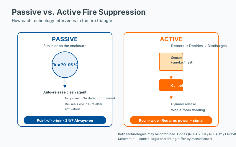 Passive vs active fire suppression comparison
Passive fire suppression is fundamentally different from the sprinklers, extinguishers, and gas flooding systems most people picture when they think of fire protection. It requires no external power, no detection-and-control system, and no human intervention — yet under the right conditions it can suppress a fire at its point of origin within seconds. For facility managers, electrical engineers, and risk consultants dealing with an ever-growing population of enclosed electrical and electronic equipment, understanding how passive suppression works is becoming essential.
This guide explains the engineering, chemistry, and physics behind the technology, the standards that govern it, where it excels, and where it should not be relied upon.
What Makes a Fire Suppression System “Passive”?
A fire suppression system is classified as passive when it operates without active triggering mechanisms, human action, or external energy input. Three defining characteristics separate passive devices from active systems:
- No external power required — there is no electrical supply, no control panel, and no battery backup. The device cannot fail because of a power outage.
- No detection system needed — the device activates purely from the thermal energy of the fire itself. There is no flame detector, smoke sensor, or aspirating network in the activation chain.
- Always-on protection — once installed and within its service-life envelope, the device protects continuously, 24 hours a day, with no scheduled maintenance visits to maintain its suppression capability.
Active systems, by contrast, depend on a chain of components that must all function correctly: a detector (smoke, heat, flame, or aspirating), a control panel, a power supply (often with mandated battery backup per NFPA 72), a release mechanism (solenoid, pneumatic valve, or pyrotechnic actuator), and the agent storage. Each link in that chain is a potential failure point, which is why active systems require periodic inspection and testing under standards such as NFPA 25 (water-based), NFPA 2001 (clean agent), and ISO 14520 (gaseous).
Passive suppression collapses that chain to a single component.
The Engineering of Microencapsulated Clean Agents
The most advanced passive fire suppression devices use microencapsulated clean agents — a technology originally developed for aerospace and military applications and now migrating into commercial infrastructure.
The Suppression Agent
The active chemical is typically FK-5-1-12, a fluorinated ketone marketed under various trade names (3M Novec 1230 being the most widely referenced). It is one of the fourth-generation replacements for halon, which was phased out under the Montreal Protocol due to its ozone depletion potential of around 7.
| Property | FK-5-1-12 | Comparison Notes |
|---|---|---|
| Ozone Depletion Potential (ODP) | 0 | Equal to CO₂ in this respect |
| Global Warming Potential (GWP, 100-yr) | 1 | Roughly 1/3000 of HFCs |
| Atmospheric Lifetime | ~5 days | vs. 14–32 years for HFCs |
| Boiling Point | 49 °C (120 °F) | Stored as liquid, dispensed as gas |
| NOAEL (No Observed Adverse Effect Level) | 10 % v/v | High safety margin in occupied spaces |
| Cup-Burner Extinguishing Concentration (heptane) | ~3.5–4 % | Efficient concentration |
FK-5-1-12 extinguishes fire through two complementary mechanisms:
- Heat absorption (physical mechanism) — the liquid vaporizes rapidly at the flame zone, absorbing significant latent heat and cooling the fuel below its ignition temperature.
- Chemical interference (kinetic mechanism) — fluorine-containing species catalytically disrupt the radical chain reactions (H•, OH•, O•) that sustain combustion. This is the same mechanism by which halons and other halogenated agents act.
Critically, the agent leaves zero residue. Unlike dry chemical (monoammonium phosphate or ABC powder), water, or foam, FK-5-1-12 does not damage printed circuit boards, switchgear, optical equipment, or stored media. After discharge, the agent simply dissipates, and the equipment can be inspected and returned to service once the fire cause is determined.
The Microencapsulation
The liquid agent is encapsulated within microscopic polymer shells — typically 50–200 µm in diameter — and these capsules are dispersed throughout a solid polymer matrix formed into a flexible patch, strip, or sachet.
The encapsulation must solve a difficult engineering problem:
- Mechanical stability — capsules must survive shipping, installation, vibration, and years of thermal cycling without rupturing.
- Thermal stability — capsules must remain intact at the upper bound of normal operating temperature (often 80 °C, sometimes higher inside enclosures) but rupture reliably at the activation setpoint.
- Chemical compatibility — the shell polymer must not react with the fluorinated ketone over a multi-year shelf life, which is typically 10+ years.
In practice, the polymer matrix is engineered to soften and burst at a defined activation temperature, releasing the agent as a vapor directly into the enclosure atmosphere.
The Activation Sequence
When a fire initiates inside an enclosure containing a passive suppression patch, the following sequence occurs:
- Incipient phase — the fire grows from ignition. Local temperatures rise, but only marginally inside the enclosure air volume.
- Thermal escalation — within typically 30–90 seconds for an electrical fire, hot plumes and buoyancy-driven convection raise the internal air temperature near the device.
- Capsule rupture — at approximately 170 °C (338 °F) at the device surface, the polymer shell reaches its softening point and the internal FK-5-1-12 flashes to vapor.
- Local agent discharge — the entire agent payload (typically 50–300 g per patch) is released essentially instantaneously into the small enclosure volume.
- Extinguishment — because the patch is already inside the equipment, the agent reaches design concentration within the fire zone in 3–5 seconds, suppressing the combustion chain reaction before the fire can establish a runaway growth curve.
The activation setpoint is selected to be well above any plausible normal operating temperature (which protects against false activation) but well below the autoignition temperature of common enclosure materials.
Why Point-of-Origin Suppression Matters
Traditional room- or building-level suppression floods a large volume with extinguishing agent. This approach has well-documented drawbacks:
- Large agent quantities — design concentrations for gaseous flooding systems are typically calculated against the net protected volume per NFPA 2001 or ISO 14520, often requiring hundreds of kilograms of agent for a single server room.
- Delayed detection — ceiling-mounted smoke detectors typically trigger at obscuration levels of 1.5–3 %/m or at temperatures well above ambient, by which time the fire may have developed significantly. Aspirating detection (very early smoke detection, or VESDA) improves this but adds substantial cost and complexity.
- Collateral disruption — clean-agent flooding typically requires HVAC shutdown, damper closure, door sealing, and sometimes power shedding, plus a pre-discharge alarm and evacuation delay (often 30 seconds) to allow personnel to escape. The protected space is unusable for the duration.
- Lifecycle cost — pressurized cylinders require annual inspection per NFPA 2001, six-year hydrostatic testing, and refilling after any discharge — whether accidental or actual fire. Maintenance contracts are a recurring operational expense.
- Single point of failure — if the detection or release chain fails, the entire protected volume is unprotected.
Point-of-origin suppression inverts every one of these trade-offs:
| Factor | Room Flooding | Point-of-Origin (Passive) |
|---|---|---|
| Agent quantity | Hundreds of kg | Grams per device |
| Activation time | 30–90 s after detection | 3–5 s from thermal trigger |
| Detection required | Yes | No |
| Power required | Yes | No |
| Annual maintenance | Yes | Typically none |
| Collateral disruption | Whole room/building | Affected enclosure only |
| Single-point failure risk | High | Low (distributed devices) |
For modern infrastructure — densely packed, electrically powered, often unattended — the case for treating each enclosure as its own fire zone is increasingly compelling.
Applications Where Passive Suppression Excels
Passive fire patches are particularly well-suited to enclosed electrical and electronic equipment, especially where the fire risk originates inside a sealed or mostly sealed volume. Common applications include:
- Server racks and network cabinets — protect individual racks without affecting a data center’s broader gas suppression system, and continue protecting during maintenance when gaseous systems are often impaired.
- Lithium-ion battery cabinets and BESS enclosures — address thermal runaway risk in energy storage; UL 9540A and NFPA 855 govern the broader system, but in-enclosure suppression reduces propagation.
- Electrical distribution panels and motor control centers — provide always-on protection in unmanned substations, pump stations, and remote plant.
- Telecom shelters and outdoor cabinets — remote sites where maintenance visits are infrequent and reliability is paramount.
- EV charging pedestals and DC fast-charging stations — integrate fire protection directly into the asset without external water or detection infrastructure.
- CNC machines and automated manufacturing cells — protect high-value automated equipment where any downtime is costly.
- UPS cabinets and battery-backed power systems — critical power protection without the maintenance burden of a sprinkler or gas system.
- Wind turbine nacelles and pitch/yaw cabinets — environments difficult to inspect and where fire consequence is severe.
In each case, the common pattern is: enclosed volume, electrical fire risk, value of continuity, and a hostile or remote location.
Standards, Listings, and Compliance
Passive suppression devices sit at a relatively new intersection of several standards regimes. The most relevant references include:
- UL 2775 — Standard for Fixed Condensed Aerosol Extinguishing System Units (analogous framework, though not all passive devices are aerosols).
- NFPA 2001 — Standard on Clean Agent Fire Extinguishing Systems (covers the agent itself and total-flooding design).
- NFPA 12, 12A, 12B — Standards on various extinguishing systems, occasionally referenced for suppression principles.
- ISO 14520 — Gaseous fire-extinguishing systems (international counterpart to NFPA 2001).
- EN 14972-1 — Fixed firefighting systems — water mist systems (relevant when considering hybrid protection).
- ASTM E84 / UL 723 — Surface burning characteristics, sometimes required for the polymer matrix.
- NFPA 855 — Standard for the Installation of Stationary Energy Storage Systems, applicable to BESS deployments.
- IEC 62673 — High-density data center cooling and related infrastructure considerations.
Independent third-party listing (UL, FM Approvals, VdS, LPCB, CNPP) provides meaningful assurance that a device has been tested against a published extinguishment protocol. Listing status should always be verified before specifying any passive suppression device on a project.
Limitations and Engineering Boundaries
Passive fire patches are not a universal solution. They work best when the following conditions are met:
| Condition | Requirement |
|---|---|
| Enclosure | Must be enclosed (sealed or mostly sealed) to retain agent concentration long enough for extinguishment |
| Volume | Typically 0.1–3 m³ per patch; larger volumes require multiple patches or supplementary protection |
| Ambient temperature | Must remain below the activation setpoint minus safety margin during normal operation |
| Fire type | Most effective on Class A (solids), Class B (liquids), and Class C (electrical) fires — the categories most relevant to electrical enclosures |
| Ventilation | High airflow enclosures (forced-air cooling, open louvers) may dilute the agent below effective concentration and require larger or multiple devices |
Critical limitations include:
- Ventilation and dilution — if the enclosure has significant airflow (e.g., a forced-air-cooled inverter cabinet with multiple fans), the agent concentration may fall below the extinguishing threshold before the fire is fully suppressed. Engineering analysis is required.
- Multiple fires — a single device protects only its own immediate volume. If a fire can establish in two separate enclosures simultaneously (rare but possible in some battery arrays), one device cannot cover both.
- Deep-seated fires — once a fire has spread into the mass of cable bundles, battery cells in thermal runaway, or smoldering insulation, even successful suppression of the visible flame may not halt the underlying chemical reaction. Suppression at the incipient phase is essential.
- Service life verification — manufacturers rate devices for a finite service life (typically 5–15 years). Records of installation dates and a replacement program are essential operational disciplines.
The Bottom Line
Passive fire suppression — particularly microencapsulated clean agent technology — represents a meaningful shift in how we think about fire protection. Instead of protecting entire buildings and hoping the fire does not spread, it stops the fire where it starts. For the growing population of enclosed, electrically-powered systems that modern infrastructure depends on — from data centers and telecom shelters to battery storage and EV charging — passive point-of-origin suppression is often the most practical, cost-effective, and reliable option available.
It is not a replacement for every fire protection measure. Active detection, sprinkler systems, and compartmentation remain essential at the building level. But at the equipment level — inside the cabinet, the rack, the enclosure — passive suppression closes a critical gap that traditional architectures have left open.
Frequently Asked Questions
What maintenance records should facility managers keep?
Maintenance records should include the as-installed configuration (device type, location, date of installation), the inspection schedule and results, any replacements or repairs, and the dates of any incident events. NFPA 10 and most insurer guidance require these records to be retained for the life of the installation. Digital records with timestamps simplify audit and incident review.
How does enclosure sealing affect suppression effectiveness?
Enclosure sealing determines how long the suppression agent remains at design concentration. An unsealed enclosure will lose agent through openings faster than the fire can be suppressed; a properly sealed enclosure retains concentration long enough to interrupt the reaction chain. Gasket condition, cable entry sealing, and ventilation management are therefore integral to the suppression design, not separate concerns.
How do I calculate the appropriate suppression capacity?
Suppression capacity is determined by the protected enclosure volume, the fire load, and the specific suppression agent. For gaseous systems, design concentration targets are defined in NFPA 2001 and ISO 14520; for passive point-of-origin devices, the manufacturer's tested performance for the specific enclosure volume and geometry applies. Engineering judgment, supported by manufacturer data and, where relevant, third-party listing, is required.
Is third-party certification required for passive suppression devices?
Third-party certification is not always required by code, but it is strongly preferred and often effectively required by AHJs and insurers. A listing from a recognized certification body (UL, FM, VdS, and similar) demonstrates that the device has been tested to a published standard and that production is audited. Unlisted devices should be evaluated carefully and supported by independent test data.