Guides # How to Detect Fire Risk in Enclosed Electrical Equipment Passive Fire Patch Editorial Team 2026-08-07 ## 1. Why Enclosed Electrical Equipment Demands a Dedicated Fire-Risk Strategy
Enclosed electrical equipment — including medium- and low-voltage switchgear, motor control centres (MCC), distribution panels, battery enclosures, and industrial control cabinets — concentrates three fire precursors in a very small volume: heat, electrical stress, and combustible insulation. Because the enclosure restricts airflow and conceals early indicators, a fault that would visibly smoulder in open air can escalate to arcing, overpressure, or flashover inside the cabinet long before any external sign is apparent.
The economic and safety consequences are significant. Insurance data consistently ranks electrical failure among the top three ignition sources for large-loss industrial fires. Standards bodies have responded by formalising inspection and monitoring expectations: NFPA 70B (2023 edition) shifted from a recommended maintenance programme to a mandatory one in many jurisdictions, NFPA 76 (Standard for the Fire Protection of Telecommunications Facilities) addresses battery rooms specifically, IEC 61936-1 covers power installations, and EN 50172 / EN 50545 address emergency lighting and associated detection. Selecting the right combination of detection technologies — and integrating them into a written risk-based inspection programme — is now a baseline expectation for engineers, specifiers, and facility managers.
This article walks through the physics of in-cabinet fire risk, the four detection modalities most commonly applied, the frameworks that govern inspection frequency, and practical sensor placement strategies for the three most common equipment classes.
2. The Physics of In-Enclosure Fire Initiation
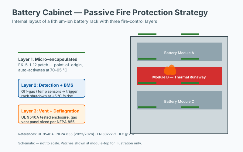 Three-layer fire protection in a battery cabinet
Fire risk in electrical cabinets is fundamentally a chain of pre-ignition events that progress through three stages:
- Insulation degradation — thermal ageing, chemical attack, moisture ingress, or mechanical stress reduce the dielectric strength of PVC, XLPE, EPR, paper, or epoxy insulation. Resistance begins to drift.
- Partial discharge (PD) activity — micro-voids, surface contamination, or loose connections produce repetitive micro-arcs that further erode insulation and produce heat, ozone, and low-molecular-weight gases.
- Thermal runaway and ignition — sustained overcurrent, a bolted fault, or a tracking event raises localised temperatures past the pyrolysis threshold of adjacent polymers (typically 300–400 °C for XLPE, lower for PVC). Off-gassing accelerates, smoke is produced, and — if an arc forms — copper or aluminium vapour adds to the energy release.
Detecting the first two stages is dramatically cheaper and safer than detecting the third. This is why modern fire-risk detection for enclosed electrical equipment emphasises trend-based condition monitoring rather than alarm-only smoke detection.
3. Thermal Imaging: The First-Line Inspection Tool
3.1 Principle
Infrared thermography converts emitted long-wave infrared radiation (typically 8–14 μm) into temperature maps. Most modern cameras used in electrical work have noise-equivalent temperature differences (NETD) of 0.05–0.10 °C and can resolve sub-degree temperature differences at the typical 1–3 m working distance.
3.2 Standards Governing Thermographic Surveys
- NFPA 70B §11.17 (2023) — requires infrared (IR) thermographic inspection as part of the routine maintenance programme, with intervals based on equipment criticality and environmental severity. The table-driven default interval is annual for most equipment, semi-annual for equipment in harsh environments, and quarterly for critical infrastructure such as emergency power, healthcare, and data centre switchgear.
- ANSI/NETA MTS-2023 — defines acceptance criteria: a 1 °C difference between similar components under similar load indicates an Indication; a 4–15 °C delta a Minor Discrepancy; a 16–35 °C delta a Moderate; and greater than 35 °C a Severe condition requiring immediate corrective action.
- ISO 18434-1 — condition monitoring using IR, including emissivity correction procedures.
- IEC 60270 / IEC 62478 — complementary PD techniques that often accompany thermography in advanced surveys.
3.3 Best-Practice Procedure
- Establish baseline loading. Survey under at least 40 % of nameplate load; below this, defects may be masked.
- Correct emissivity. Use manufacturer-published values (anodised aluminium ≈ 0.77, painted steel ≈ 0.94, aged busbar ≈ 0.85) or apply known-temperature tape.
- Compare like with like. Phase-to-phase, pole-to-pole, similar cubicles in the same lineup.
- Document ambient temperature and load so that trending over time is meaningful.
3.4 Limitations
Thermography is fundamentally a snapshot of surface temperature. A bolted fault inside a busbar joint may produce hot spots that radiate outward slowly, while a rapidly developing arc can reach 20 000 °C in milliseconds — visible in the infrared but undetectable if no scan was in progress at that moment. This is why thermography must be paired with continuous monitoring for high-criticality assets.
4. Continuous Thermal Monitoring
For substations, data centres, and process-critical switchboards, fixed infrared window-based or non-contact pyrometric systems provide continuous coverage.
4.1 Sensor Placement Strategies
- Crystal/IR windows: Installed in cabinet doors or side panels to allow fixed cameras to image busbars, cable terminations, breakers, and busways without opening the enclosure. This preserves arc-flash boundaries (NFPA 70E) and IP ratings.
- Pyrometric probes: Point sensors aimed at busbar joints, bolted connections, and breaker spouts. Provide lower spatial resolution but excellent temporal resolution and lower cost.
- Linear heat detection (LHD): Fibre-optic or digital linear heat cables routed along cable trays entering or exiting the cabinet. Useful where the risk is dominated by cable insulation rather than busbar joints.
4.2 Alarm Thresholds
- Pre-alarm: 10 °C above maximum expected operating temperature, but below historical maximum for the asset.
- Alarm: 20 °C above expected, or rate of rise > 2 °C/min sustained for > 5 min.
- Trip: 35 °C above expected, or any rate of rise > 5 °C/min.
These figures are typical starting points; site-specific baseline trending should refine them within the first year of operation.
5. Smoke Detection: Aspirating and Point-Type
5.1 Why Standard Smoke Detection Struggles in Cabinets
Ceiling-mounted optical or ionisation detectors are designed for open-space fires. Smoke from an in-cabinet fault must first overcome the enclosure’s IP rating, then dilute into a large volume before reaching the detector. By the time a ceiling detector alarms, the cabinet may already have reached flashover. Standards such as NFPA 72 are explicit that spot detectors shall be listed for the environment; placing a standard ceiling detector directly inside an enclosed cabinet is rarely compliant.
5.2 Aspirating Smoke Detection (ASD)
Very early warning aspirating systems (often termed VEWFD per NFPA 72) draw a controlled airflow through a network of sampling pipes. Inside the cabinet, a manifold of capillary tubes with drilled or laser-drilled holes can sample each compartment, returning to a central detector with high-sensitivity laser or LED chambers.
- Typical sensitivity: 0.005 % obs/m — sufficient to detect a smouldering cable fault many hours before conventional detectors.
- Filtered inlet prevents false alarms from dust.
- EN 54-20 / ISO 7240-20 classify ASD into Class A (very high sensitivity), B (enhanced), and C (ordinary).
5.3 Spot-Type Cabinets and Air Sampling Modules
For smaller cabinets, miniature sampling modules mount directly inside and communicate with the fire alarm panel via addressable loops. They typically provide Class B/C equivalent sensitivity in a footprint of 100 × 100 × 30 mm and operate on the same loop as ceiling devices.
5.4 Sensor Placement Strategies for Smoke Detection
- Sample at the top of the enclosure — hot smoke stratifies.
- Place sample holes above cable entries and above breaker compartments, where insulation materials pyrolyse first.
- Avoid sampling directly in front of ventilation openings — short-circuiting the airflow reduces detection efficiency.
- Where possible, pair with a heat sensor in the same cabinet. Smoke plus heat confirmation dramatically reduces nuisance alarms from dust.
6. Gas Sensing: CO, H₂, and Off-Gassing Signatures
6.1 The Chemistry of Pre-Fire Off-Gassing
Long before visible particles are emitted, electrical faults decompose insulation and produce characteristic gases. The most commonly exploited markers:
MarkerTypical SourceBackground LevelTypical Alarm ThresholdHydrogen (H₂)PD activity, especially in oil-impregnated paper, XLPE under high field stress< 2 ppm10–100 ppm depending on equipment classCarbon monoxide (CO)Smouldering insulation, pyrolysis of PVC/XLPE/EPR< 5 ppm10–50 ppmCarbon dioxide (CO₂)Oxidation of insulation; produced alongside COAmbient 400 ppmRising trend rather than absolute valueAcetylene (C₂H₂)Arcing — distinct marker< 1 ppm1–2 ppmMethane/Ethane (CH₄/C₂H₆)Lower-temperature oil faults< 10 ppmRising trendTotal VOC / TVOCGeneric insulation off-gassingSite dependent2–3× baseline
6.2 Standards and Interpretation
- IEEE C57.104 — guide for dissolved gas analysis (DGA) in oil-immersed transformers, providing the canonical interpretation framework (Rogers ratios, Duval triangles). Although written for oil, the gas-pair logic is informative for dry insulation also.
- IEC 60599 — companion international standard.
- NFPA 70B §11.18 — explicitly references gas monitoring as part of an emerging best-practice programme for enclosed equipment.
- CIGRE TB 525 / TB 771 — guidance for gas monitoring of GIS and dry-type equipment.
6.3 Sensor Technology Choices
- Electrochemical cells — excellent for CO and H₂ at low ppm; limited life (typically 2–3 years in clean air); cross-sensitivity to other gases must be accounted for.
- Non-dispersive infrared (NDIR) — reliable for CO₂, hydrocarbon vapours; less suitable for H₂.
- Metal-oxide semiconductor (MOS) — broad-spectrum VOC detector; cheap; non-specific.
- Pellistor / catalytic bead — combustible gas detection; unsuitable for H₂-only targeting due to poisoning.
- Photoacoustic infrared — high-sensitivity multi-gas analysis in a single bench unit; appropriate for central detection at the switchroom level.
6.4 Sensor Placement Strategies
- Place sensors at the top of the cabinet — most fault gases are lighter than air and stratify upward.
- For tall cabinets (> 2 m), place at mid-height on the rear wall — catches both rising gases and gases pooling behind busbars.
- For battery enclosures, place near the cell vents where off-gassing occurs; account for hydrogen being lighter than air.
- Use one sensor per phase compartment in three-phase switchgear to localise the faulted phase.
- Calibrate against a documented baseline at commissioning**, then alarm on rate of change rather than absolute level for low-confidence species.
7. Partial Discharge (PD) Monitoring
7.1 Why PD Matters
Partial discharges are micro-arcs that occur within insulation voids, on contaminated surfaces, or at loose interfaces. Each PD event releases a few picocoulombs to several nanocoulombs of charge. Repetitive activity degrades insulation and is the leading indicator of impending dielectric failure.
7.2 Detection Modalities
- Ultra-high frequency (UHF) — capacitive or UHF couplers detect electromagnetic emissions in the 300 MHz – 3 GHz band. Standard for GIS (IEC 62271-203) and increasingly applied to air-insulated switchgear.
- Transient Earth Voltage (TEV) — surface-mounted couplers detect the fast voltage transients that couple through metalwork. Common in MV switchgear.
- Acoustic emission — piezoelectric sensors detect the ultrasonic pressure wave from each discharge. Good for pinpointing location; tolerant of electromagnetic interference; less sensitive to PD inside solid insulation.
- HFCT (High-Frequency Current Transformer) — clamped around cable earth straps or cable screens; detects the high-frequency pulse currents of PD. Cost-effective for cable terminations.
- UV imaging — detects corona discharge by its UV signature (240–280 nm). Useful for outdoor insulators; limited inside enclosures.
- Dielectric loss / tan-delta — bulk-insulation characterisation rather than event counting; complementary, not competing.
7.3 Interpretation
PD is interpreted by magnitude, repetition rate, phase position relative to the 50/60 Hz cycle, and trend. Modern instruments (per IEC 62478 / IEC 60270) provide phase-resolved PD patterns that classify the defect type — corona, floating electrode, internal void, surface tracking, or particle effect.
NFPA 70B §11.19 lists PD testing as a recommended technique in the condition-monitoring section, and CIGRE WG B3.06 provides guidance on permanent PD monitoring for AIS.
7.4 Sensor Placement Strategies
- TEV: One per accessible metal panel — typically door, side, rear — of each switchgear cubicle.
- Acoustic: Pair as a triangulation network; minimum three sensors per zone, no more than 3 m apart, with line-of-sight.
- HFCT: At every cable termination entering the cabinet; on the earth strap between cable screen and ground bus.
- UHF: At cable entry ports in GIS; in dry-type transformer tank sections.
8. Risk Assessment Frameworks
Detection technology must be selected within a documented risk framework. Three are widely used:
8.1 NFPA 70B Equipment Risk Assessment (2023 Edition)
NFPA 70B now embeds a risk-based maintenance methodology. Each piece of equipment is scored on:
- Equipment condition (age, history, manufacturer EOL)
- Criticality (impact of failure on safety, operations, or revenue)
- Operating environment (temperature, humidity, dust, corrosive atmosphere)
The resulting matrix drives inspection interval, technology selection (visual, thermographic, PD, gas), and documentation depth.
8.2 IEC 60300 / ISO 31000 Risk Management
For international projects, ISO 31000 provides the generic process: establish context, identify hazards, analyse likelihood and consequence, evaluate, treat, monitor, review. Within an electrical asset portfolio, each cabinet is treated as a risk unit with quantitative or semi-quantitative scoring.
8.3 API RP 580 / 581 (Adapted)
Although written for process industries, the risk-based inspection (RBI) approach is increasingly applied to switchgear in oil-and-gas and heavy-industrial facilities. POF (probability of failure) is informed by condition monitoring data; COF (consequence of failure) by safety, environmental, and financial exposure. The combined risk drives the inspection plan.
9. Inspection Intervals per NFPA 70B
The table below summarises typical NFPA 70B (2023) intervals for enclosed electrical equipment. Always confirm against the latest edition and local jurisdiction.
Equipment TypeVisual / MechanicalThermographyPD MonitoringGas SensingMV Switchgear (≥ 1 kV)12 mo12 mo12 mo (continuous for critical)12 moLV Switchgear / MCC12 mo12 moOptional24 moCritical Switchgear (data centres, hospitals, emergency power)6 mo6 moContinuous recommended6 moHarsh Environment (mining, outdoor, chemical)6 mo6 mo6 mo6 moBattery Rooms (VRLA / Li-ion)3 mo——Continuous for H₂ (Li-ion) and CO (VRLA)Cable Trays / Bus Ducts12 mo12 mo24 mo (HFCT)—
A condition-based interval reduction is permitted when trending data indicates declining condition, with formal re-evaluation annually.
10. Sensor Placement Summary by Equipment Class
10.1 Switchgear (MV and LV)
- Top interior: aspirating smoke sampling point.
- Each phase compartment: electrochemical H₂ and CO sensor.
- Cable terminations: HFCT on earth strap.
- Cubicle exterior panels: TEV couplers (MV) or acoustic sensors.
- IR window: in door, aligned with busbar joints and breaker spouts.
- Ambient: switchroom-level ASD for early awareness.
10.2 Motor Control Centres (MCC)
- Per drawer column: aspirating sample point above each vertical section.
- Per bucket: thermal probe aimed at line-side lugs.
- Per compartment: low-cost MOS TVOC sensor for trend.
- Bus: IR window on door.
- Consider a single combined multi-gas unit serving three or four columns to balance cost.
10.3 Control Cabinets and PLC Panels
- Door: aspirating sampling manifold on top rail.
- Inside: photoelectric smoke spot detector mounted high.
- 24 V supply and I/O terminals: spot thermal sensor.
- For areas with long cable runs: linear heat cable along the cable entry duct.
- Gas sensing is rarely cost-effective in control cabinets; rely on smoke + thermal + visual inspection.
10.4 Battery Enclosures
- Ceiling of enclosure: H₂ sensor (mandatory for Li-ion installations per NFPA 855 / IEC 62619).
- Within each cell block: CO sensor for VRLA.
- Door: aspirating sample point (some Li-ion chemistries off-gas electrolyte vapour).
- Ventilation flow: ensure sensors are not placed in dead-air pockets — model the airflow.
11. Integration with the Fire Alarm and Building Management System
Detection only delivers value if it triggers a defined response. Recommended practice:
- Pre-alarm → notify control room, dispatch thermographer for verification.
- Alarm → notify fire panel, isolate the affected compartment electrically (where interlocks exist), activate suppression if
Frequently Asked Questions
How often should electrical panels undergo thermal imaging inspection?
NFPA 70B and most insurer guidance recommend annual thermographic inspection of energized electrical equipment, with more frequent inspection for critical or heavily loaded equipment. Inspections should be performed under normal operating load, with results trended over time. Identified hot spots should be investigated before the next inspection cycle.
What role does insulation resistance play in fire prevention?
Insulation resistance degradation is a leading precursor to arcing and short-circuit events in enclosed electrical equipment. Routine insulation resistance testing, typically performed during scheduled maintenance, identifies trending decline before a failure occurs. Megger testing or equivalent measurement is the standard practice, with results compared against the equipment's baseline and manufacturer specifications.
What is the leading cause of electrical fires in enclosed equipment?
Industry fire-loss data consistently identifies loose or degraded electrical connections, followed by insulation failure and overload, as the leading causes of fires in enclosed electrical equipment. Arc-flash events from these conditions can ignite adjacent insulation or combustible materials. Regular thermal imaging and insulation resistance testing target these leading causes directly.
Can arc flash be prevented by passive suppression?
Passive suppression cannot prevent an arc-flash event from initiating; it can only contain the event after it has begun. Arc-flash prevention is primarily an electrical design and maintenance question: proper working clearance, current-limiting devices, and routine connection inspection per NFPA 70E. Passive suppression can reduce the secondary consequences of an arc-flash event in an enclosure.