The Complete Guide to Passive Fire Protection
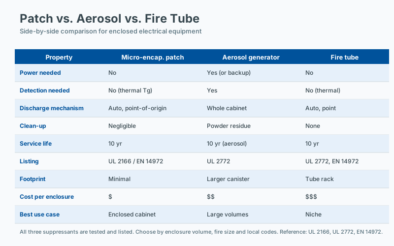 Comparing patch, aerosol generator and fire tube
Passive fire protection (PFP) is one of the most misunderstood disciplines in modern fire safety engineering. Many facility managers and even practicing engineers conflate the term with structural fireproofing, fire-resistive coatings, or compartmentation. While these are indeed branches of PFP, the discipline has expanded significantly over the past two decades — particularly at the equipment level, where fire must be suppressed at its point of origin before it can compromise a wider system.
This guide provides a comprehensive, vendor-neutral overview of passive fire protection: its definitions, regulatory framework, technology families, application domains, and integration with active suppression systems. It is written for engineers, facility managers, AHJs (authorities having jurisdiction), and procurement professionals who need a working technical reference rather than a marketing brochure.
Defining Passive Fire Protection
At its core, passive fire protection is any fire safety measure that satisfies three criteria simultaneously:
- No external activation required. No electrical signal, no mechanical actuator, no human intervention. The system must function without any external trigger beyond the fire itself.
- Automatic response to fire conditions. The system reacts directly to heat, flame, or thermal decomposition products.
- Continuous protection. The system is always “on” — there is no duty cycle, no standby state, no monthly test mode. It remains in service for its full design life without intervention.
This definition distinguishes PFP from active fire protection (AFP) systems such as sprinklers, water mist, gaseous suppression, or foam systems, all of which require detection, control, and actuation sequences. PFP is sometimes described as “fire protection that doesn’t know it’s there” — until it matters.
Two Domains of PFP
Modern PFP spans two largely separate — but occasionally overlapping — engineering domains:
Structural PFP addresses the building fabric itself: fire-resistant walls, floors, ceilings, and doors; intumescent and cementitious coatings on structural steel; firestopping of service penetrations; cavity barriers; and fire-rated ductwork. The objective is compartmentation and structural integrity for a prescribed duration (typically 30, 60, 120, or 240 minutes) per standards such as EN 13501-2, ASTM E119, or UL 263.
Equipment-level PFP addresses individual assets — control cabinets, lithium-ion battery enclosures, server racks, EV charging pedestals, wind turbine nacelles, and similar distributed assets. The objective is to suppress a fire at its origin, prevent propagation to neighboring equipment, and limit damage to the specific asset. This is the focus of the present article.
Why Equipment-Level PFP Matters Now
Three converging trends are driving rapid growth in equipment-level PFP.
Distributed Critical Infrastructure
The proliferation of edge computing nodes, 5G base stations, distributed renewable energy assets, microgrids, and EV charging networks means critical equipment is increasingly located in unmanned, unmonitored, and often environmentally harsh spaces. Traditional active suppression systems — sprinklers, clean agent total flooding — are impractical or uneconomical when applied to thousands of small, geographically scattered enclosures.
Battery Energy Storage System (BESS) Risk Profile
Lithium-ion battery fires present unique challenges: thermal runaway, off-gassing of flammable electrolytes (typically mixtures of ethylene carbonate, dimethyl carbonate, and ethyl methyl carbonate), jet flames from cell venting, and the possibility of cascading cell-to-cell propagation. Standards such as UL 9540A, NFPA 855, and IEC 62485-2 increasingly recognize equipment-level mitigation as a necessary supplement to room-scale gas detection and ventilation. PFP solutions — intumescent panels, suppression patches, and containment barriers — directly address the propagation problem.
Cost and Insurance Pressures
Insurers, particularly those underwriting data center and BESS exposures, are increasingly requiring or incentivizing equipment-level mitigation. A single suppressed cabinet incident is dramatically cheaper than a total facility loss. PFP technologies that operate for 10–15 years without maintenance align well with the service intervals of the assets they protect.
Key Standards and Regulatory Framework
PFP at the equipment level sits at the intersection of several regulatory regimes. The following table summarizes the most relevant standards as of 2026.
| Standard | Scope | Key Relevance to PFP |
|---|---|---|
| NFPA 2001 | Clean agent fire extinguishing systems | Design concentration and hold time; informs minimum agent loading for encapsulated PFP |
| NFPA 855 | Installation of stationary energy storage systems | Cabinet-level mitigation; separation distances; fire detection coordination |
| UL 9540A | Test method for evaluating thermal runaway fire propagation | Cell-to-cell propagation testing methodology |
| UL 2127 | Fire tests for electrical equipment | Enclosure fire resistance; arc-flash containment |
| EN 50600-2-5 | Data center design — security and environmental | Fire protection provisions for IT infrastructure |
| IEC 62485-2 | Secondary batteries — safety requirements for installation | Ventilation, thermal runaway protection |
| ISO 14520 | Gaseous fire-extinguishing systems (international equivalent of NFPA 2001) | Agent quantity and distribution |
| GB 50116 | China fire alarm and detection design standard | Recognition of equipment-level suppression |
| FM Global DS 5-33 | Property loss prevention data sheet for BESS | Cabinet-level mitigation, deflagration venting |
Note that PFP itself is rarely the direct subject of a named standard — most often it is referenced as a mitigation measure within broader standards for active systems or facility design.
Comparing Equipment-Level PFP Technologies
Equipment-level PFP encompasses several distinct technology families. The following comparison reflects the state of the art as of 2026.
Microencapsulated Fire Suppression Patches
These consist of a polymeric carrier matrix (often a flexible rubber or thermoplastic film) in which a clean extinguishing agent — historically halon replacements such as HFC-227ea or HFC-236fa, and increasingly FK-5-1-12 (3M Novec 1230) or other fluoroketones — is microencapsulated. At approximately 170 °C, the capsule walls fail and the agent is released directly into the fire zone.
- Trigger: Heat, typically 170–190 °C
- Agent: Clean agent (FK-5-1-12, HFC-227ea, or similar)
- Residue: None — the carrier remains as a thin film
- Service life: 10 years typical
- Limitations: Agent payload limited by patch area; best for small enclosures
Heat-Activated Fire Suppression Tubes (Fire Tube / Detection Tube)
A pressurized polymer tube routed through the protected enclosure ruptures at a predetermined temperature (typically 110–160 °C depending on the tube). The pressure drop triggers a cylinder valve, releasing a stored agent — dry chemical powder, clean agent, or water mist — through nozzles.
- Trigger: Tube rupture under heat
- Agent: Variable — dry powder, clean agent, water mist
- Residue: Powder systems leave heavy residue; clean agents leave minimal residue
- Service life: 5–10 years; pressure testing required periodically
- Limitations: Mechanical complexity, pressure vessel maintenance
Aerosol Generators (Condensed Aerosol)
Pyrotechnic or pyrolizing solid compounds (typically potassium nitrate-based) generate a fine aerosol when electrically or thermally activated. The aerosol interrupts combustion chain reactions in the gas phase.
- Trigger: Electrical signal or heat
- Agent: Potassium-based aerosol
- Residue: Heavy alkaline residue requiring cleanup
- Service life: 10+ years
- Limitations: Enclosure must be reasonably sealed; residue may damage electronics
Intumescent Panels and Coatings
Rigid panels or flexible coatings containing expanding graphite or similar intumescent compounds. Upon heating above approximately 200 °C, the material expands to form a char layer that insulates the substrate.
- Trigger: Heat, typically >200 °C
- Mechanism: Physical barrier and thermal insulation — does not extinguish fire directly
- Residue: Char layer; no chemical residue
- Service life: 15+ years
- Limitations: Suppression capability is limited; primarily propagation control
Self-Activating Suppression Boards
Hybrid products that combine intumescent substrates with embedded microencapsulated agent. They provide both insulation and chemical suppression in a single installed assembly.
- Trigger: Heat
- Mechanism: Combined thermal barrier and chemical suppression
- Service life: 10–15 years
Selection Criteria
The correct technology depends on the application. For high-value electronics with no tolerance for residue, microencapsulated patches are generally preferred. For battery cabinets where propagation control is the dominant concern, intumescent panels — possibly combined with patches — are typical. For larger enclosures, fire tubes offer higher agent payloads at the cost of mechanical complexity.
Integration with Active Fire Protection Systems
A common misconception is that PFP can replace active suppression. The correct framing is defense in depth — multiple independent layers of protection, each reducing the probability of catastrophic loss.
- Active systems protect the building fabric and occupants. Sprinklers, clean agent total flooding, water mist, and foam systems are designed and approved at the room or zone level. They require detection, control, and actuation, and they typically engage at larger fire sizes.
- Passive systems protect individual equipment at the point of origin. They engage at incipient or small fire stages, often before detection systems would register an event.
Typical integrated configurations include:
- Data centers: Room-level clean agent flooding (NFPA 2001) supplemented by in-rack passive suppression at the server cabinet level. PFP reduces the size of the initiating event, allowing the room system to perform within its design envelope.
- Battery energy storage: Room ventilation per NFPA 855, gas detection, and possibly sprinkler suppression, supplemented by cabinet-level intumescent barriers and suppression patches to prevent cell-to-cell propagation per UL 9540A test results.
- Industrial control cabinets: Sprinkler or water mist at the facility level, with suppression patches inside enclosures to address arc-flash-induced fires without contaminating the protected equipment.
- EV charging enclosures: Detection and alarm systems at the parking level, with suppression patches inside charging pedestals to address connector and cable fires.
In each case, the PFP layer reduces the initiating event’s severity and improves the probability that active systems will succeed.
Engineering and Installation Considerations
Beyond technology selection, several practical engineering factors determine whether a PFP installation will perform as designed.
Enclosure integrity. PFP functions best in reasonably tight enclosures. Gaps, ventilation openings, and unsealed cable penetrations allow agent or aerosol to escape before reaching extinguishing concentration. Where enclosures cannot be sealed, designers should account for leakage in their agent quantity calculations.
Thermal exposure profile. The trigger temperature of the PFP element must be matched to the expected thermal exposure. A patch rated for 190 °C may not function in a fire that develops rapidly to higher temperatures; conversely, a low-trigger patch may be susceptible to nuisance activation during normal high-temperature operation (e.g., near resistance heating elements).
Service environment. Humidity, vibration, UV exposure, and chemical atmosphere all affect PFP service life. Manufacturers typically publish accelerated aging data; designers should verify that the local environment falls within tested bounds.
Maintenance and inspection. Most PFP devices have no consumable parts and require only visual inspection during routine facility maintenance. However, periodic verification — typically annual — of physical condition, trigger temperature certification (for replaceable elements), and installation integrity is recommended.
Documentation and code compliance. Installation must be documented per local code requirements. In jurisdictions following NFPA, installation records and manufacturer certifications should be retained for AHJ inspection. Under EN 50600 and related European frameworks, CE marking and DoP (Declaration of Performance) documentation apply.
Future Directions
Several trends are reshaping equipment-level PFP. Climate-neutral refrigerants and low-global-warming-potential agents are increasingly substituting for older HFCs. Integrated sensing — PFP elements with embedded sensors that report health status to building management systems — is moving from prototype to commercial reality. Standards bodies, including NFPA and IEC, are gradually codifying equipment-level PFP as a recognized mitigation layer, particularly for BESS applications. The result is a maturing discipline that complements — rather than competes with — traditional active suppression.
Frequently Asked Questions
How do I calculate the appropriate suppression capacity?
Suppression capacity is determined by the protected enclosure volume, the fire load, and the specific suppression agent. For gaseous systems, design concentration targets are defined in NFPA 2001 and ISO 14520; for passive point-of-origin devices, the manufacturer's tested performance for the specific enclosure volume and geometry applies. Engineering judgment, supported by manufacturer data and, where relevant, third-party listing, is required.
Is third-party certification required for passive suppression devices?
Third-party certification is not always required by code, but it is strongly preferred and often effectively required by AHJs and insurers. A listing from a recognized certification body (UL, FM, VdS, and similar) demonstrates that the device has been tested to a published standard and that production is audited. Unlisted devices should be evaluated carefully and supported by independent test data.
What is the first step in assessing fire risk for an enclosure?
The first step is to identify the fire load (what can burn, in what quantity, and with what energy release), followed by the credible ignition sources and the pathways to propagation. Standards such as NFPA 76 and NFPA 855 provide structured assessment methods for specific equipment types. A documented risk assessment is the basis for selecting any suppression technology.
What maintenance records should facility managers keep?
Maintenance records should include the as-installed configuration (device type, location, date of installation), the inspection schedule and results, any replacements or repairs, and the dates of any incident events. NFPA 10 and most insurer guidance require these records to be retained for the life of the installation. Digital records with timestamps simplify audit and incident review.