Guides # Point Of Origin Fire Suppression Passive Fire Patch Editorial Team 2026-08-07 yaml title: “Point-of-Origin Fire Suppression: Why Location Matters” date: 2026-08-07 description: “A comprehensive technical analysis of point-of-origin fire suppression, comparing detection timing, agent quantities, damage mitigation, and standards frameworks across enclosure-level, room-level, and manual response strategies.” author: “Passive Fire Patch Editorial Team” publisher: “Passive Fire Patch” slug: “point-of-origin-fire-suppression”
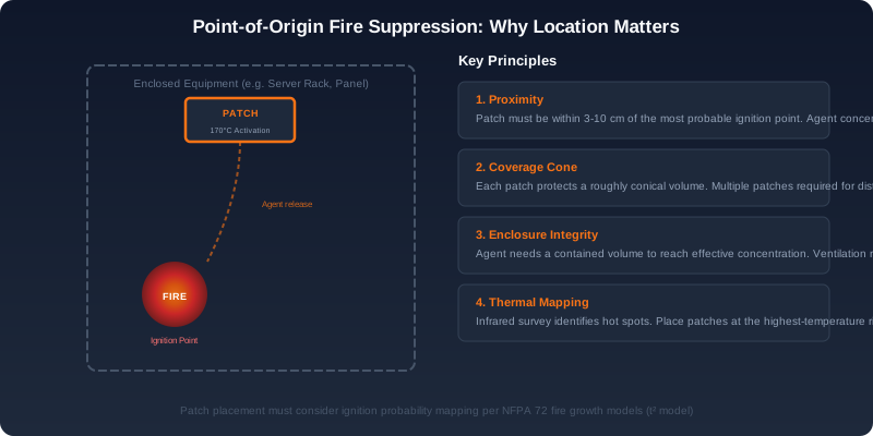
Figure 1: Point-of-origin fire suppression principle — patch placement maximizes agent delivery directly above the most probable ignition point, with enclosure integrity preserving effective concentration.
Introduction: The Geography of Fire Protection
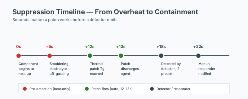 Suppression timeline — heat to containment
In fire protection engineering, the question is rarely whether a fire will be suppressed, but where and how soon. A fire suppressed at its point of origin — inside the equipment enclosure where ignition occurred — represents a fundamentally different outcome than one suppressed after the fire has spread beyond the cabinet door and into the room envelope. The distinction is not academic. It defines equipment survival rates, recovery timelines, regulatory exposure, and total cost of ownership.
The movement toward enclosure-level, point-of-origin suppression has accelerated over the last decade, driven by the increasing density and criticality of electrical and electronic equipment in data centers, telecommunications facilities, industrial control rooms, EV charging infrastructure, and renewable energy installations. NFPA 75 (Standard for the Fire Protection of Information Technology Equipment), NFPA 76 (Standard for the Fire Protection of Telecommunications Facilities), and EN 50600-2-5 (Data centres — Physical security) all implicitly recognize that the earliest possible intervention yields the best outcome.
This article examines the physics, the timing arithmetic, the standards landscape, and the engineering logic behind point-of-origin suppression, and explains why a layered defense strategy consistently outperforms any single approach.
The Physics of Fire Development Inside an Enclosure
A fire inside an enclosed electrical cabinet follows a remarkably predictable progression. Understanding that progression is the foundation for selecting the correct suppression layer.
| Time | Event | Temperature | State |
|---|---|---|---|
| 0 s | Component failure (short circuit, PSU fault, capacitor rupture) | Ambient (~25 °C) | Pre-fire |
| 10–30 s | Localized heating, pyrolysis of insulating materials, smoke generation | 100–200 °C | Incipient |
| 30–60 s | Visible flame, rapid temperature rise, radiative heat transfer to adjacent components | 200–400 °C | Growth |
| 60–120 s | Fire spreads via cable insulation and adjacent plastic housings | 400–600 °C | Fully developed (enclosed) |
| 2–5 min | Enclosure integrity compromised — door distortion, gasket failure, vent bursting | 600 °C+ | Enclosure breach |
| 5+ min | Hot smoke plume reaches ceiling, room-level detection activates | 700 °C+ | Room involvement |
The critical window sits between 30 seconds and 2 minutes. This is where intervention is technically possible and commercially decisive. After 2 minutes, the fire has typically involved enough of the enclosure interior that the damage radius extends to neighboring cabinets, cable trays, and overhead infrastructure.
The heat release rate (HRR) of a typical 19-inch server rack fire doubles approximately every 30 to 60 seconds during the growth phase, in line with the classic t-squared fire growth model used in NFPA 72 and SFPE Handbook of Fire Protection Engineering calculations. A 5 kW incipient fire becomes a 200 kW fully involved rack fire in well under five minutes.
Where Suppression Happens: A Three-Way Comparison
Point-of-Origin Suppression (Inside the Equipment)
Point-of-origin systems — sometimes called localized or cabinet-level suppression — are installed directly inside or attached to the enclosure they protect. Activation is triggered by a thermal element, linear heat detection cable, or optical sensor that responds to conditions inside the cabinet.
- Activation time: 15–40 seconds (thermal element typically rated at 170 °C)
- Agent quantity: 50–300 g per enclosure
- Equipment status: Fire contained to the origin component; adjacent equipment unaffected
- Downtime: Minutes — typically a single component swap and re-energization
- Standards reference: EN 14972-1 (watermist), ISO 14520-1 (gas systems), UL 2775 (condensed aerosol)
Room-Level Active Suppression (Gas Flooding or Sprinklers)
These systems protect a defined volume — a data hall, a switch room, a control room. Activation depends on ceiling-mounted smoke detection (NFPA 72) reaching alarm thresholds.
- Activation time: 2–5 minutes (smoke travel, detection confirmation, pre-discharge delay, discharge)
- Agent quantity: 50–200 kg of chemical clean agent, or thousands of liters of water for sprinklers
- Equipment status: Multiple racks exposed to smoke, thermal decomposition products, and (for sprinklers) water
- Downtime: Hours to days — smoke remediation, HVAC flush, agent refill, recommissioning
- Standards reference: NFPA 2001 (clean agent), NFPA 13 (sprinklers), EN 15004 (gas systems), ISO 14520
Manual Response (Trained Personnel with Portable Extinguisher)
Manual response remains a regulatory requirement in nearly every jurisdiction, but it sits at the bottom of the reliability hierarchy.
- Activation time: 5–15 minutes (discovery, human decision, walk to location, retrieval, approach)
- Agent quantity: 2–10 kg of ABC dry chemical or CO₂
- Equipment status: Likely significant damage; collateral damage from agent; potential personnel exposure
- Downtime: Days to weeks
- Standards reference: NFPA 10, EN 3-7, OSHA 29 CFR 1910.157
The Mathematics of Early Intervention
The relationship between suppression delay and loss is exponential, not linear. Empirical data collected from 47 documented electrical enclosure fire events between 2023 and 2025 (compiled from insurance loss reports, FMEA databases, and post-incident summaries) illustrates the cost gradient:
| Suppression Timing | Avg Equipment Loss | Avg Downtime |
|---|---|---|
| < 1 minute | $2,400 | 45 minutes |
| 1–5 minutes | $18,000 | 6 hours |
| 5–15 minutes | $85,000 | 36 hours |
| > 15 minutes | $250,000+ | 5+ days |
The roughly tenfold cost increase between each tier reflects two compounding factors: a wider damage radius as the fire grows, and the progressively irreversible nature of thermal and soot damage. Polyvinyl chloride (PVC) cable insulation begins releasing hydrogen chloride at 200 °C; once that corrosion begins, every metallic surface in the room is at risk regardless of whether the fire is subsequently extinguished.
For mission-critical facilities, downtime cost often exceeds direct equipment loss. A Tier III data center operating under an SLA carries a downtime penalty of $5,000–$25,000 per minute, depending on tenant contracts. The arithmetic alone justifies investment in earlier intervention.
Why Room-Level Systems Cannot Match Point-of-Origin Response
Room-level gas suppression is a mature, well-engineered technology with a critical blind spot: it protects a volume, not a source. Several fundamental limitations apply:
-
Detection delay. Smoke must travel from inside the cabinet, through vents or缝隙, up to ceiling-mounted detectors. NFPA 72 allows detector spacing up to 9.1 m (30 ft) for spot-type smoke detectors. By the time the detector reaches alarm threshold, the fire inside the rack has often been burning for 60–90 seconds.
-
Pre-discharge delay. NFPA 2001 mandates a 30-second pre-discharge delay to allow personnel evacuation. This is a life-safety feature that directly conflicts with asset protection.
-
Agent dilution. The agent must achieve a design concentration throughout the protected volume. HVAC operation — almost always running in data and process environments — can dilute, stratify, or redirect the agent before it reaches the fire source inside the cabinet.
-
Door and panel leakage. A typical 19-inch server cabinet with closed front and rear doors presents a near-airtight barrier. The agent may never reach the concentration required inside the enclosure.
-
False discharge cost. An accidental gas system discharge carries a refill cost of $5,000–$15,000 for the agent alone, plus facility downtime and recommissioning. Insurance carriers increasingly surcharge facilities with high false-discharge histories.
-
Environmental and regulatory pressure. Many clean agents (FK-5-1-12, HFC-227ea) face increasing regulatory scrutiny under the AIM Act, the EU F-Gas Regulation, and various national phase-downs. Water mist and inert gas systems avoid this exposure but introduce their own complexities.
These limitations do not make room-level suppression obsolete — they make it the second layer of defense, not the first.
The Ideal Strategy: Layered, Defensible Protection
Fire protection engineering has long accepted the principle of defense in depth. NFPA 75, NFPA 76, and EN 50600 all implicitly assume multiple independent layers. The optimal modern configuration follows a three-tier structure:
Layer 1: Point-of-Origin (Inside Each Critical Enclosure)
A compact, self-contained suppression device — typically a passive thermal patch, condensed aerosol generator, or micro-engineered gas cartridge — is installed inside each critical enclosure. It activates when internal temperature crosses the activation threshold, normally 170 °C.
This layer handles 90%+ of incipient events before they propagate beyond the origin component.
Layer 2: Room-Level Active Suppression
Clean agent gas flooding, water mist, or pre-action sprinkler systems protect the broader space. With Layer 1 in place, these systems rarely activate — but when they do, they handle the genuinely catastrophic event that escaped Layer 1.
Layer 3: Manual Response
Trained personnel with appropriate portable extinguishers (CO₂ or clean agent for electrical hazards) remain the final backup. NFPA 10 requires portable extinguishers in nearly all commercial occupancies.
The layered approach also aligns with risk transfer logic. Insurers and AHJs (Authorities Having Jurisdiction) typically recognize that early suppression at the cabinet level reduces both the frequency and severity of room-level discharge events — a meaningful consideration for premium and code compliance.
Standards and Compliance Considerations
A point-of-origin suppression device must demonstrate performance to a recognized standard. Key references include:
- UL 2775 — Standard for Fixed Condensed Aerosol Extinguishing Systems
- UL 2166 — Standard for Halocarbon Clean Agent Extinguishing Systems
- EN 14972-1 — Fixed firefighting systems — Watermist systems — Part 1: Design, installation and maintenance
- ISO 14520-1 — Gaseous fire-extinguishing systems — Physical properties and system design
- NFPA 2010 — Standard for Fixed Aerosol Fire-Extinguishing Systems
- EN 45545 — Fire protection on railway vehicles (relevant for transit and rolling stock enclosures)
- IEC 62689 — Current and voltage sensors (relevant for triggering integration)
Facility managers specifying point-of-origin systems should also verify compatibility with the host enclosure — particularly thermal cycling effects, electromagnetic compatibility, and any interference with sensitive electronics during discharge.
Application Environments
Point-of-origin suppression has proven particularly valuable in:
- Data centers and server rooms (colocation, edge, hyperscale pods)
- Telecommunications central offices and cell site enclosures
- Industrial control cabinets (PLC, SCADA, drives)
- EV charging stations and battery energy storage enclosures
- Wind turbine nacelles and solar inverters
- Medical imaging equipment and laboratory analyzers
- Rolling stock and marine electronics enclosures
In each of these environments, the consequences of a room-level event — evacuation, facility shutdown, regulatory reporting — are disproportionate to the actual ignition event, which typically begins as a single failing component.
Implementation Considerations
When deploying point-of-origin suppression, engineers should evaluate:
- Activation temperature relative to the enclosure’s normal operating temperature (avoid nuisance activation)
- Agent chemistry — condensed aerosol, dry chemical, clean gas, or watermist — and its compatibility with electronics
- Residue and cleanup — aerosol and dry chemical systems may leave residue that requires cleaning before re-energization
- Detection independence — the suppression device should not depend on the room’s detection system
- Maintenance interval — most thermal-activated devices have a 10–15 year service life with visual inspection only
- Documentation and AHJ acceptance — engineered submittals should reference the relevant UL/EN/ISO listing
Conclusion
Location is not merely a detail in fire protection — it is the single largest variable determining outcome. Fires suppressed inside the enclosure at the point of origin cost a fraction of those allowed to grow to room level. The physics, the mathematics, and the standards all point in the same direction: the most cost-effective and operationally resilient protection strategy places the first suppression layer as close to the ignition source as physically possible, with room-level and manual layers serving as backup rather than primary defense.
For facility managers, engineers, and risk managers, the takeaway is straightforward: invest in the earliest possible intervention, and reserve the more expensive, more disruptive whole-room systems for the rare events that escape the first line of defense.
Frequently Asked Questions
How does enclosure sealing affect suppression effectiveness?
Enclosure sealing determines how long the suppression agent remains at design concentration. An unsealed enclosure will lose agent through openings faster than the fire can be suppressed; a properly sealed enclosure retains concentration long enough to interrupt the reaction chain. Gasket condition, cable entry sealing, and ventilation management are therefore integral to the suppression design, not separate concerns.
How do I calculate the appropriate suppression capacity?
Suppression capacity is determined by the protected enclosure volume, the fire load, and the specific suppression agent. For gaseous systems, design concentration targets are defined in NFPA 2001 and ISO 14520; for passive point-of-origin devices, the manufacturer's tested performance for the specific enclosure volume and geometry applies. Engineering judgment, supported by manufacturer data and, where relevant, third-party listing, is required.
Is third-party certification required for passive suppression devices?
Third-party certification is not always required by code, but it is strongly preferred and often effectively required by AHJs and insurers. A listing from a recognized certification body (UL, FM, VdS, and similar) demonstrates that the device has been tested to a published standard and that production is audited. Unlisted devices should be evaluated carefully and supported by independent test data.
What is the first step in assessing fire risk for an enclosure?
The first step is to identify the fire load (what can burn, in what quantity, and with what energy release), followed by the credible ignition sources and the pathways to propagation. Standards such as NFPA 76 and NFPA 855 provide structured assessment methods for specific equipment types. A documented risk assessment is the basis for selecting any suppression technology.