Guides # Sizing A Fire Patch Passive Fire Patch Editorial Team 2026-08-07 yaml title: “How to Size a Fire Patch for Enclosed Equipment” date: 2026-08-07
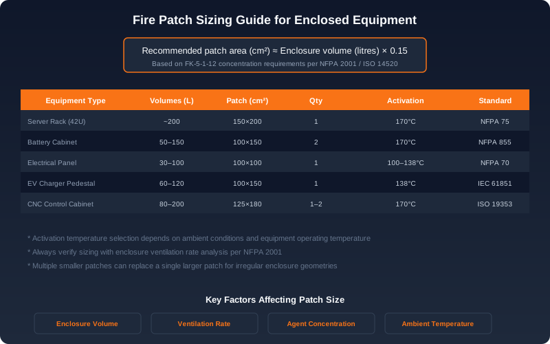
Figure 1: Recommended fire patch dimensions by equipment type, based on enclosure volume and relevant standards. Multiple smaller patches may be used for irregular geometries.
Correctly sizing a fire suppression patch inside an enclosed equipment cabinet is the single most important engineering decision in a clean-agent local application system. Under-sizing risks failure to reach the minimum extinguishing concentration, allowing the fire to propagate beyond the protected volume. Over-sizing wastes capital, occupies valuable space inside the cabinet, and can introduce unnecessary pressure-rise concerns during discharge. This guide walks through the engineering methodology, references to relevant standards, common mistakes, and practical placement guidance used by designers across the data center, battery energy storage, and industrial control sectors.
Why Sizing Matters
 Patch placement in battery cabinet modules
Fire patches — small, thermally activated or electrically initiated devices that release a clean gaseous extinguishing agent — are local application systems per NFPA 2001 (Standard on Clean Agent Fire Extinguishing Systems) and the European EN 15004 (Fixed Firefighting Systems – Gas Extinguishing Systems – Design, Installation, and Maintenance) annexes covering local application. Unlike total flooding systems, where the agent concentration is verified across an entire sealed room, local application systems are intended to achieve the design concentration only within the immediate hazard volume — typically the inside of an enclosure.
Because the agent is discharged from a single point and must reach every protected surface within seconds, the relationship between enclosure volume, agent mass, discharge time, and physical obstructions becomes critical. The agent must reach a minimum design concentration — typically 4 % to 6 % by volume for fluoroketone (FK-5-1-12), 5.2 % being a typical Class A/B design point — and maintain that concentration long enough to suppress the fire and cool hot surfaces below re-ignition temperature.
A patch that delivers only 3 % concentration in a 1.5 m³ switchgear cabinet will not extinguish a persistent electrical fire; the insulation will continue to pyrolyze, and the fire will re-flash as soon as the agent dissipates through leakage. Conversely, doubling the agent mass in a 0.3 m³ control panel doubles the discharge pressure transient, may over-pressurize a lightweight enclosure, and offers no engineering benefit.
Fundamental Design Principle
The physics of local application fire suppression follows a straightforward mass-balance equation:
m_agent = V_free × C_design × ρ_agent × SF
Where:
- m_agent = required agent mass (grams)
- V_free = internal free air volume of the enclosure (m³)
- C_design = design concentration as a decimal (e.g., 0.052 for 5.2 %)
- ρ_agent = density of the agent vapor at the design concentration and reference temperature (g/m³)
- SF = safety factor accounting for leakage, ventilation, and computational uncertainty
For FK-5-1-12 at 5.2 % concentration and 20 °C ambient, ρ_agent ≈ 72 g/m³. For HFC-227ea (FM-200) at the equivalent design concentration of 6.25 %, ρ_agent ≈ 56 g/m³. For N₂ / IG-541 (Inergen) at 37.5 % design concentration, ρ_agent ≈ 540 g/m³, but the design philosophy is total flooding and the application geometry differs considerably. Always confirm agent density values from the manufacturer’s certified design data, as they vary with temperature.
Step-by-Step Sizing Methodology
Step 1: Calculate Enclosure Internal Volume
Begin with the manufacturer’s mechanical drawing and obtain the internal dimensions of the enclosure — never use external footprint, and never include door swing volumes.
V_gross = W × D × H (m³)
Most enclosures list internal volume in their specifications; if not, subtract wall thickness (typically 1.5–2.5 mm for steel, 3–5 mm for aluminum).
Next, subtract the volume occupied by installed equipment. A fully populated 42U server rack typically shows 40 %–60 % free air volume, depending on cable density, blanking panel usage, and the type of equipment installed. A high-density battery rack with prismatic lithium iron phosphate cells may drop to as low as 25 % free air volume; a sparsely populated telecommunications cabinet may exceed 75 %.
V_free = V_gross − V_equipment
Step 2: Determine Required Agent Mass
Plug the free volume into the mass-balance equation.
Example: A 19-inch server rack with internal dimensions 0.6 m × 1.0 m × 2.0 m and 50 % free air volume:
- V_gross = 1.2 m³
- V_free = 0.6 m³
- Agent mass = 0.6 × 0.052 × 72 ≈ 2.25 g of FK-5-1-12
- With a safety factor of 1.5 → 3.4 g
Compare this to the more typical real-world example quoted in legacy literature for a 1.2 m³ free volume (a fully populated rack with limited equipment): 1.2 × 0.052 × 72 ≈ 4.5 g, plus safety factor ≈ 5.85 g. The point is that internal free volume — not the rack’s nominal footprint — drives the calculation.
Step 3: Apply a Safety Factor
NFPA 2001 requires a minimum safety factor of 1.3 on the calculated agent quantity for sealed enclosures, with additional allowances for openings. For local application inside equipment enclosures, most designers apply 1.3–2.0, depending on confidence in the volume calculation and enclosure leak rate.
| Condition | Recommended Safety Factor |
|---|---|
| Hermetically sealed enclosure | 1.3 |
| Cabinet with gasketed door, no fans | 1.4 |
| Cabinet with cable penetrations (≤ 1 % opening area) | 1.5 |
| Cabinet with active ventilation (fan stops on detection) | 1.5 |
| Cabinet with active ventilation (fan continues running) | 2.0–3.0 |
Step 4: Account for Ventilation and Forced Air Cooling
Ventilation is the dominant loss mechanism for clean agents. According to NFPA 2001 Annex A, an enclosure with forced-air cooling will lose agent through the same paths that admit cooling air. The treatment depends on control integration:
- If fans interlock with the detection system (stop on agent discharge or on first-stage alarm), standard local application sizing applies — the patch discharges into a quiescent volume and the agent has time to reach design concentration.
- If fans continue running, the patch must overcome a continuous agent loss rate. The required mass scales roughly with the volumetric airflow through the enclosure. A 200 CFM (0.094 m³/s) fan can purge agent from a 1 m³ enclosure in under 11 seconds — faster than most patches achieve full discharge. For these cases, multiply the required agent by 1.5× to 3.0× depending on airflow rate and whether the discharge plume is upstream or downstream of the fire.
UL 2166 (Outline of Investigation for Halocarbon Clean Agent Extinguishing System Units) and FM Global Property Loss Prevention Data Sheet 5-72 (FM Global, Clean Agent Fire Extinguishing Systems) both emphasize airflow integration testing for local application designs in ventilated equipment.
Step 5: Select the Patch Size
Standard commercial patch sizes are typically grouped into coverage bands rather than precise single-volume ratings. Common bands:
| Patch Mass | Approximate Coverage (FK-5-1-12) | Typical Application |
|---|---|---|
| 50 g | 0.5–1.0 m³ | Small electrical panels, control consoles |
| 100 g | 1.0–2.0 m³ | Standard 42U server rack |
| 200 g | 2.0–3.5 m³ | Large server rack, small BESS cabinet |
| 300 g | 3.5–5.0 m³ | Large enclosures, switchgear cabinets |
| 500 g | 5.0–8.0 m³ | BESS enclosures, large drive cabinets |
These coverage ranges already include a typical safety factor; verify with the specific manufacturer’s UL-listed or EN-tested design curves before final selection. Coverage figures also assume a single unobstructed compartment — divided enclosures require separate calculations for each sub-volume.
Step 6: Placement Within the Enclosure
Even a correctly sized patch will fail if poorly placed. The physics of buoyant gas dispersion favors elevated mounting:
- Mount at the top of the enclosure whenever possible. Clean agents are denser than air at room temperature (FK-5-1-12 vapor density ≈ 7.3 × air), so they sink and fill downward, but a top-mounted discharge minimizes stratification losses and ensures the plume does not immediately interact with the floor-level leak paths.
- Position above or adjacent to the highest-probability ignition sources: power supply units, battery modules, DC busbars, high-current terminals, and densely packed PCB assemblies. UL 9540A test data on lithium-ion BESS consistently identifies these as primary ignition locations.
- Maintain an unobstructed dispersion path. A patch mounted behind a cable bundle or behind a hard drive cage will discharge into a stagnation zone. NFPA 2001 recommends a minimum clearance equal to the smaller dimension of the protected volume on at least one face.
- For multi-compartment enclosures, place one patch per compartment. Internal dividers prevent cross-compartment agent migration.
Common Sizing Mistakes
After hundreds of design reviews, the same errors recur across projects. Avoiding them saves money and, more importantly, saves the protected asset:
- Using external dimensions. External dimensions include wall thickness and may include mounting flanges, plinths, or roof-mounted fans — all of which inflate the calculated volume and produce an under-sized agent charge.
- Ignoring equipment fill. A nominal “2 m³ rack” may have only 0.8 m³ of free air space once servers, cable management, and PDUs are installed. Designers who use the cabinet’s gross volume consistently under-size.
- Omitting the safety factor. Real enclosures leak. Cable penetrations, door gaps, and convection vents all contribute. A calculated minimum without margin is a calculated failure under realistic conditions.
- Single patch for divided enclosures. A patch mounted in one compartment will not protect an adjacent sealed compartment. Each independently sealed volume requires independent analysis per NFPA 2001.
- Neglecting altitude and temperature. Agent density is a strong function of ambient conditions. A design prepared at sea level at 20 °C under-suppresses at high-altitude data centers (Denver, Mexico City) or in unconditioned outdoor enclosures.
- Treating “coverage volume” as exact. Manufacturer-stated coverage values are typically conservative for an ideal geometry. They are not a substitute for a documented calculation traceable to NFPA 2001 or EN 15004.
When to Use Multiple Smaller Patches
There are several legitimate engineering reasons to deploy multiple patches instead of one large patch in the same enclosure:
- Internal obstructions (large transformers, mid-rails, divider panels) create shadow zones a single discharge point cannot reach within the agent’s mixing time.
- Distributed fire risk — for example, a BESS cabinet with two independent battery strings — benefits from local patch placement adjacent to each risk cluster, shortening the discharge-to-extinguishment interval.
- Redundancy. A single patch is a single point of failure. Critical infrastructure (data centers, telecom PoPs, substation control houses) often requires N+1 redundancy, with two patches sized for full coverage such that either alone can suppress the design fire.
- Pressure-rise management. Large single discharges generate a measurable pressure transient inside a sealed enclosure. Per NFPA 2001 Annex B, if the pressure rise approaches 2.5 kPa (250 mm H₂O), the enclosure may require a pressure-relief vent. Splitting the discharge across two patches halves the peak pressure and may eliminate the need for relief hardware.
Standards and References
A defensible sizing calculation should reference at least the following standards:
- NFPA 2001 – Standard on Clean Agent Fire Extinguishing Systems (design concentrations, safety factors, local application)
- NFPA 76 – Standard for the Fire Protection of Telecommunications Facilities (enclosure geometry and ventilation)
- EN 15004-1 – Gas extinguishing systems – Design, installation, and maintenance (European equivalent)
- ISO 14520-1 – Gaseous fire-extinguishing systems – Physical properties and system design
- UL 2166 – Halocarbon Clean Agent Extinguishing System Units
- FM Global DS 5-72 – Clean Agent Fire Extinguishing Systems
- UL 9540A – Test Method for Evaluating Thermal Runaway Fire Propagation (BESS)
- NFPA 855 – Standard for the Installation of Stationary Energy Storage Systems
Verification and Commissioning
A calculation alone does not prove performance. Best practice — and the requirement of most Authorities Having Jurisdiction (AHJs) — is to verify the design after installation. Methods include:
- Door fan pressurization test (per NFPA 2001 Annex C) to confirm the enclosure’s actual leakage area.
- Concentration measurement with a portable clean-agent analyzer during a mock discharge.
- Discharge integrity test with the patch initiated electrically but with the agent safely vented.
The as-installed agent concentration should equal or exceed the design concentration throughout the protected volume for the specified hold time (typically 10 minutes minimum for Class A hazards, longer for deep-seated Class B risks).
Frequently Asked Questions
What maintenance records should facility managers keep?
Maintenance records should include the as-installed configuration (device type, location, date of installation), the inspection schedule and results, any replacements or repairs, and the dates of any incident events. NFPA 10 and most insurer guidance require these records to be retained for the life of the installation. Digital records with timestamps simplify audit and incident review.
How does enclosure sealing affect suppression effectiveness?
Enclosure sealing determines how long the suppression agent remains at design concentration. An unsealed enclosure will lose agent through openings faster than the fire can be suppressed; a properly sealed enclosure retains concentration long enough to interrupt the reaction chain. Gasket condition, cable entry sealing, and ventilation management are therefore integral to the suppression design, not separate concerns.
How do I calculate the appropriate suppression capacity?
Suppression capacity is determined by the protected enclosure volume, the fire load, and the specific suppression agent. For gaseous systems, design concentration targets are defined in NFPA 2001 and ISO 14520; for passive point-of-origin devices, the manufacturer's tested performance for the specific enclosure volume and geometry applies. Engineering judgment, supported by manufacturer data and, where relevant, third-party listing, is required.
Is third-party certification required for passive suppression devices?
Third-party certification is not always required by code, but it is strongly preferred and often effectively required by AHJs and insurers. A listing from a recognized certification body (UL, FM, VdS, and similar) demonstrates that the device has been tested to a published standard and that production is audited. Unlisted devices should be evaluated carefully and supported by independent test data.